234
Control function
10.2.3.1.3 Compensation from Room thermostat
There are max. 4 room thermostats that can be incorporated to each Water Cycle (Cycle 1 and Cycle 2). Compensate
water temperature setting by room temperatures and room setting temperature on the specic cycles (Cycle 1 & 2) to
operate space cooling/cooling eciently.
This function is available with the following possible combinations:
● Rooms function on Master controller is selected as room thermostat. Optional Auxiliary sensor on PCB1 of indoor unit
can be congured as function of Room_amb1...7 and be selected as Room temperature detection. Refer to 10.10.
● Slave_Wired room controller can be selected as room thermostat.
When Room compensation is enabled, the calculated set point is adjusted according on the dierence between the Room
temperature and room setting temperature. The amount of room inuence can be adjusted by the Room temperature
compensation factor setting.
To increase or decrease the amount of room compensation, the room compensation factor should be adjusted.
(1) Cycle 1
The conguration of this option should be done through the master controller
Conguration → Space cooling→ Cycle 1→Room temperature Compensation
Mark Description Default Value Range Steps Units
Rfactc_c1 Compensation factor OFF OFF-1-5 1 °C
Maxfactc _c1 Max Compensation value 5 0~5 1 °C
Minfactc _c1 Min Compensation value -5 -5~0 1 °C
Compenc_c1= Rfactc_c1 × Maximum dierence of room temperature and room setting temperature for
Thermo ON Rooms on Cycle 1
Minfactc _c1 ≤ Compenc_c1 ≤ Maxfactc _c1
(2) Cycle 2
The conguration of this option should be done through the master controller
Conguration → Space cooling→ Cycle 2→Room temperature Compensation
Mark Description Default Value Range Steps Units
Rfactc_c2 Compensation factor OFF OFF-1-5 1 °C
Maxfactc _c2 Max Compensation value 5 0~5 1 °C
Minfactc _c2 Min Compensation value -5 -5~0 1 °C
Compenc_c2= Rfactc_c2 × Maximum dierence of room temperature and room setting temperature for
Thermo ON Rooms on Cycle 2
Minfactc _c2 ≤ Compenc_c2 ≤ Maxfactc _c2
NOTE
:
1. [Compensation factor] on Conguration set as [OFF] to inactive room thermostat compensation.
2. Use room thermostat compensation to decrease target outlet water temperature dynamically according to room cooling
load with relative high set-point.
10.2.3.2
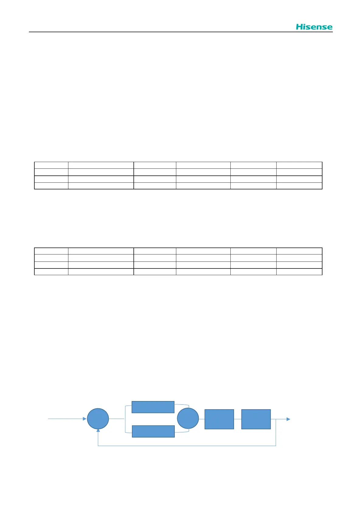
Second water temperature control
The mixing valve is controlled to maintain the second cooling supply temperature at the second cooling target outlet water
temperature. The mixing valve position is calculated with a proportional integral action (P+I) control algorithm based on the
dierence between the cooling target outlet water temperature and the cooling supply temperature.
Cycle 2 mixing valve position
P(PB)
Z
Cycle 2 Target outlet
water temperature
+
Cycle 2 outlet water
temperature
Tow2
⊿T
Mixing
valve
Outlet
water
I(IRF)
Tow2
-
Where:
PB: Proportional band of mixing valve.
IRF: Integral reet factor of mixing valve.
RTV: running time factor of mixing valve.