226
Control function
(2) Cycle 2
The conguration of this option should be done through the master controller.
Conguration → Space heating → Cycle 1→Room temperature Compensation
Mark Description Default Value Range Steps Units
Rfacth_c2 Compensation factor 2 OFF-1-5 1 °C
Maxfacth _c2 Max Compensation value 10 0~10 1 °C
Minfacth _c2 Min Compensation value -10 -10~0 1 °C
Compenh_c2= Rfacth_c2 × Maximum dierence of room setting temperature and room temperature for
Thermo On Rooms on Cycle 2
Minfacth _c2 ≤ Compenh_c2 ≤ Maxfacth _c2
NOTE:
1. [Compensation factor] on Conguration set as [OFF] to inactive room thermostat compensation.
2. Use room thermostat compensation to increase target outlet water temperature dynamically according to room heating
load with relative low set-point.
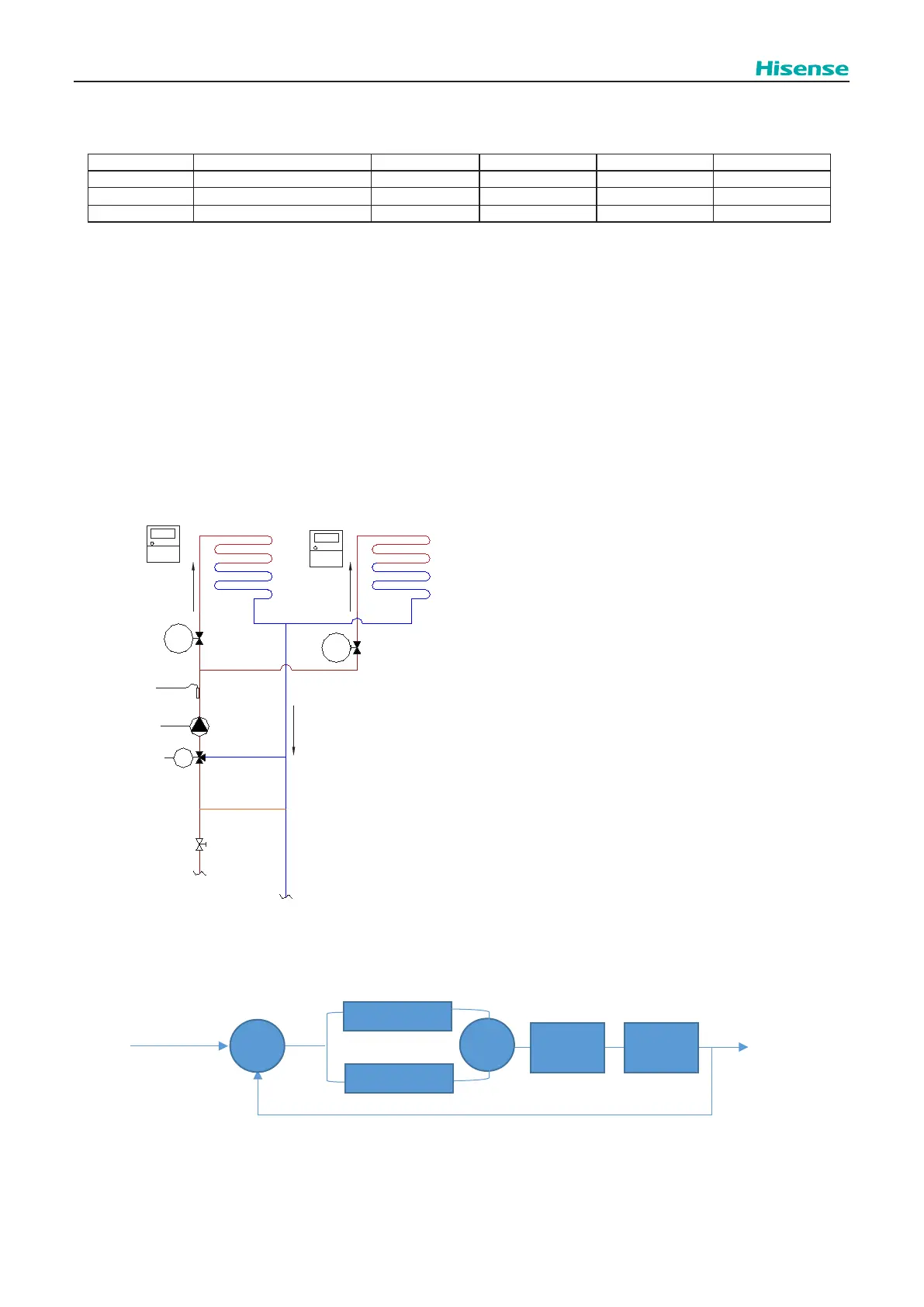
10.2.2.2
Second water temperature control
The mixing valve is controlled to maintain the second heating supply temperature at the second heating target outlet water
temperature. The mixing valve position is calculated with a proportional integral action (P+I) control algorithm based on the
dierence between the heating target outlet water temperature and the heating supply temperature.
WP2
Tow2
M
ACT3
Vmix
cycle_2_room_1
Wired1
cycle_2_room_2
Wired2
ACT4
Cycle 2 mixing valve position
P(PB)
Z
Cycle 2 Target outlet
water temperature
+
Cycle 2 outlet water
temperature
Tow2
⊿T
Mixing
valve
Outlet
water
I(IRF)
Tow2
-
Where:
PB: Proportional band of mixing valve.
IRF: Integral reet factor of mixing valve.
RTV: running time factor of mixing valve.