384
Troubleshooting
1.3 Checking procedure for main parts
1.3.1 Functions of RSW; DSWs and LEDs
1.3.1.1
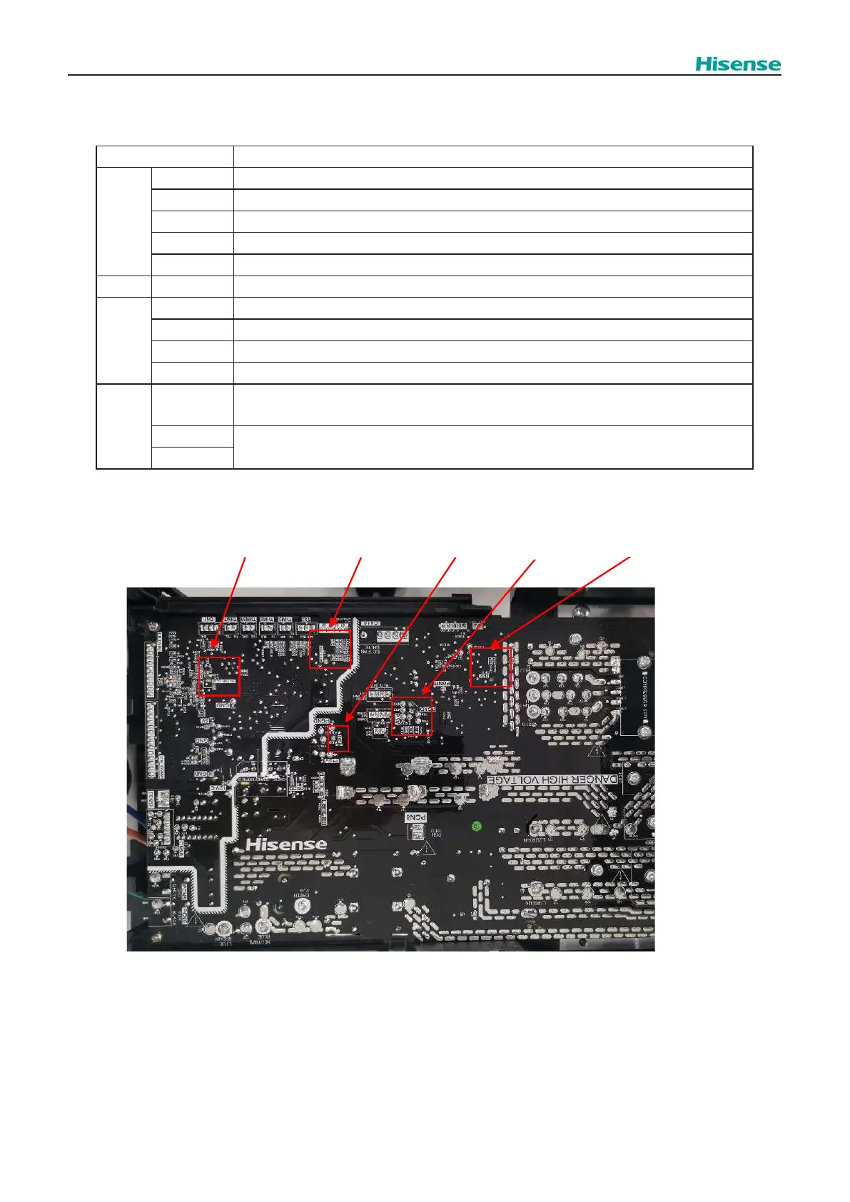
Functions of RSW; DSWs and LEDs (O.U.)
Part Name Contents
LEDs
LED1 Running status indicator of inverter on O.U. main PCB
LED1 Power Supply Indication for O.U. display PCB
LED2 Power Supply Indication for O.U. main PCB
LED700 This LED700 indicates the transmission state between the outdoor unit and indoor unit
LED802 This LED802 indicates the inverter transmission status
SEG SEG1 Indicate alarm code and check parameters
DSWs
DSW1 No setting is required
DSW3 Capacity setting
DSW5 End resistance setting
DSW6 Refrigeration system No. setting
PSWs
PSW1
Manual defrost operation switch. The defrost option is manually available under the forced defrost
area
PSW2
Available optional function. Setting can be selected using the 7-segment display
PSW3
LED1 RED
LED2 RED
LED802 RED
LED700 Yellow
P5V
O.U. main PCB