310
Troubleshooting
1.2 Troubleshooting Procedure
1.2.1 Checking of Using 7-Segment Display
The 7 segment at the indoor unit PCB1 will show the alarms from the indoor unit.
The 7 segment at the outdoor unit display PCB shows the alarms from the outdoor unit.
1.2.1.1
Checking of Using 7-Segment Display(O.U.)
1 Turn on Indoor Unit
During auto-addressing, the following items can be checked using the
outdoor unit's 7-segment on display PCB.
(1) Disconnection of power supply to the indoor unit.
(2) Reverse connection of the operating line between the outdoor and
indoor unit.
In this case, "03" appears after 30 seconds.
(3) Duplication of indoor unit number. See Alarm Code 35.
Outdoor Unit
display
PCB
2 Turn on the Outdoor Unit
3 Auto-addressing Starts
Normal
Case
(1) The outdoor unit's on-board 7-segment on display PCB is not indicated.
Abnormal
Case
(2) The outdoor unit's on-board 7-segment LED display indicates the followings if there is something wrong.
(A) Alarm code will be displayed on the 7-segment
when alarm is received from indoor unit in normal mode.
As for the following alarm codes, however, alarm code will be displayed on the 7-segment when
alarm is detected by outdoor unit itself.
Alarm Code “03” (Abnormal Transmission between Indoor Unit and Outdoor Unit)
Alarm Code “35” (Incorrect Indoor and Outdoor Unit No. Setting)
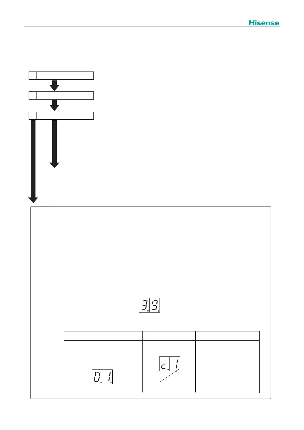
(B) The following 7-segment is displayed and flashed every 0.5 seconds.
(C) SEG1 is as follows.
7-Segment Display
<In Case of Unit Alarm Code “01”>
SEG1: Alarm Code
Dotted Indication Remarks
SEG1
Alarm Code
Dotted Indication
SEG1
The Degeneration Control is not
Activated is shown without
dotted indication.
The Degeneration Control is
Activated is shown with dotted
indication.
SEG1
Alarm Code