103
Installation
8.2.9 SPACE HEATING/COOLING AND DHW
8.2.9.1
ADDITIONAL HYDRAULIC NECESSARY
ELEMENTS
Do not connect the power supply to the unit prior to lling the
space heating circuit with water and checking water pressure
and the total absence of any water leakage.
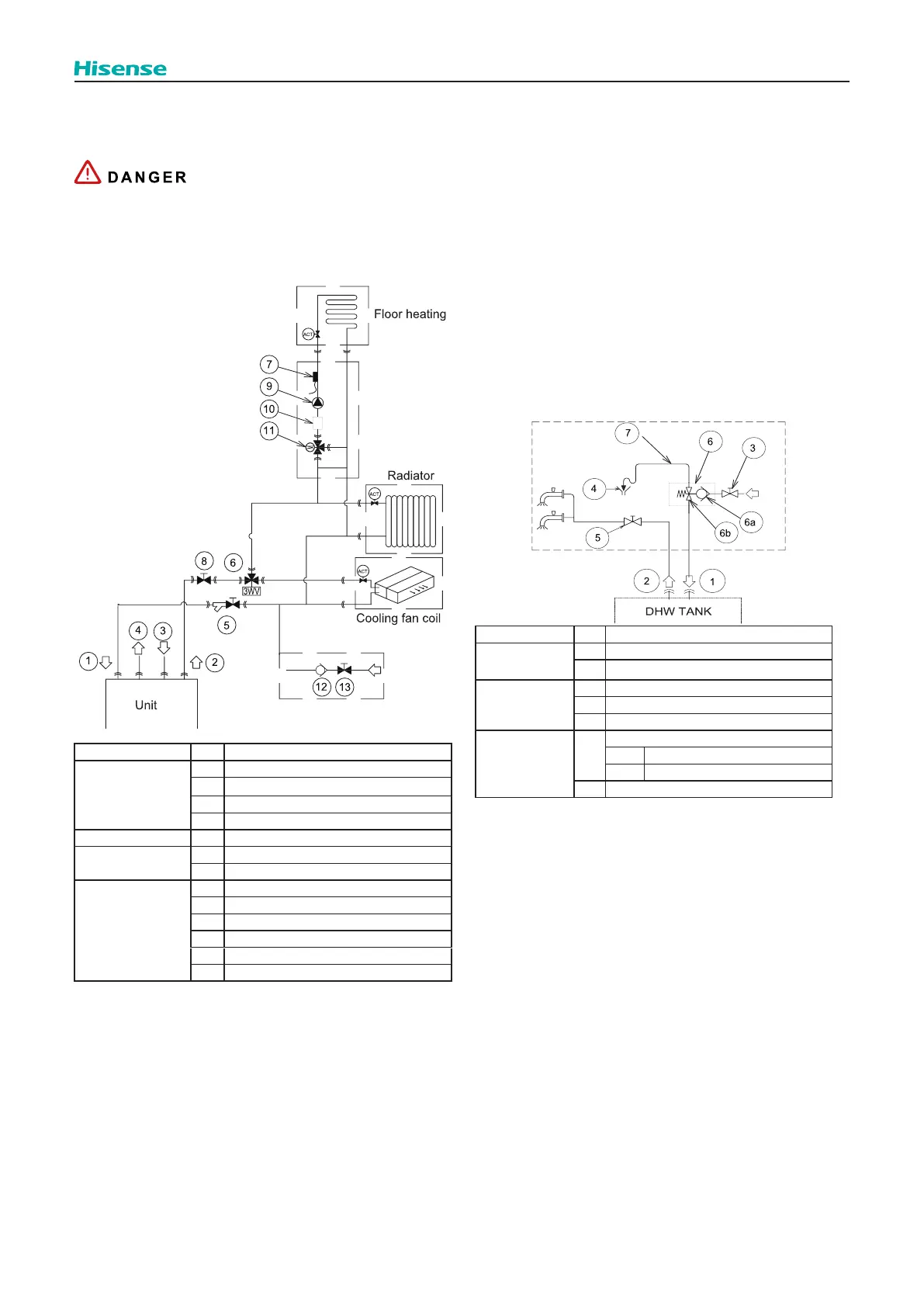
Nature No. Part name
Piping connections
1 Space heating/cooling water inlet
2 Space heating/cooling water outlet
3 DHW inlet (Cold water)
4 DHW outlet (Hot water)
Factory supplied 5
Optional
accessories
6 3WV Cooling
7 Thermistor (for Space heating))
Field supplied
8
9 Water pump
10 Filter
11 Mixing valve
12 Check valve
13
As an installation example of space heating / cooling, the
following hydraulic elements are necessary to correctly
perform the space heating / cooling water circuit:
(5) need to be installed horizontally at water inlet of the
unit.
water circuit. The check valve acts as a safety device to
protect the installation.
3-way valves (6) must be connected at one point of the
water outlet pipe of the installation, used to divert the
Space heating thermistor (7) must be installed on the
metal tube close to space heating, and keep in good
contact with it.
Mixing valve (11) is recommended to use ESBE
ARA661, whose operation mode is 3-point SPDT. If
mixing valve of other brands or models are used, the
operation mode must be 3-point SPDT, and power
supply must be 220-240V ~ 50Hz. The rotation time can
be set in the master controller.
Nature No. Part name
Piping
connections
1 DHW inlet (Cold water)
2 DHW outlet (Hot water)
Field supplied
3
4 Draining
5
Factory supplied
6
Pressure relief valve
6a Water check valve
6b Pressure relief valve
7 Drain pipe
A Shut-o valve (eld supplied):
tank outlet (2) in order to make easier any maintenance
work.
A Pressure relief valve (Factory supplied):
The domestic hot water tank must be fed with cold water
passing through a pressure relief valve (6) calibrated to
about 7 bar (depending on local regulations). Operate
the pressure relief valve according to manufacturer’s
the pressure relief valve (6) and the tank. The pressure
relief valve (6) must be installed as near as possible to
the DHW inlet and connected to a drain pipe (7) leading
to the sewer. This pressure relief valve can provide the
following:
- Pressure protection
- Non-return function
- Filling
- Draining
8.2.9.1.1 Elements for space heating/cooling
8.2.9.1.2 Elements for DHW
As an installation example of Domestic hot water (DHW), the
following hydraulic elements are necessary to correctly
perform the DHW water circuit:
(1) Elements required for the DHW water circuit
Check the pressure relief valve on the cold water supply
inlet.
The pressure relief valve must be operated regularly to
remove scale deposits and verify that it is not blocked.