65
Installation
8.1.7 PIPING WORK
Make sure that refrigerant piping installation complies with
the legislation EN378 and local legislation.
8.1.7.1
GENERAL NOTES BEFORE PERFORMING
PIPING WORK
Prepare locally-supplied copper pipes.
Select the piping size with the correct thickness and
Select clean copper pipes. Make sure that there is no
dust or moisture inside the pipes. Blow the inside of the
pipes with oxygen free nitrogen to remove any dust and
foreign materials before connecting them.
A system with no moisture or oil contamination will give maximum
performance and lifecycle compared to that of a poorly prepared
system. Take particular care to ensure that all copper piping is clean
and dry internally.
Cap the end of the pipe when pipe is to be inserted
through a wall hole.
Do not put pipes on the ground directly without a cap or
vinyl tape at the end of the pipe.
If piping installation is not completed until next day or
piping and charge with oxygen free nitrogen through a
and particle contamination.
It is advisable to insulate the water pipes, joints and
connections in order to avoid heat loss and dew
condensation on the surface of the pipes or accidental
injures due to excessive heat on piping surfaces.
Do not use insulation material that contains NH3, as it
can damage copper pipe material and become a source
of future leakage.
piping inlet and outlet in order to avoid vibration
transmission.
Refrigerant circuit and water circuit must be performed
and inspected by a licensed technician and must comply
with all relevant European and national regulations.
Proper water pipe inspection should be performed after
piping work to assure there is no water leakage in the
water circuit.
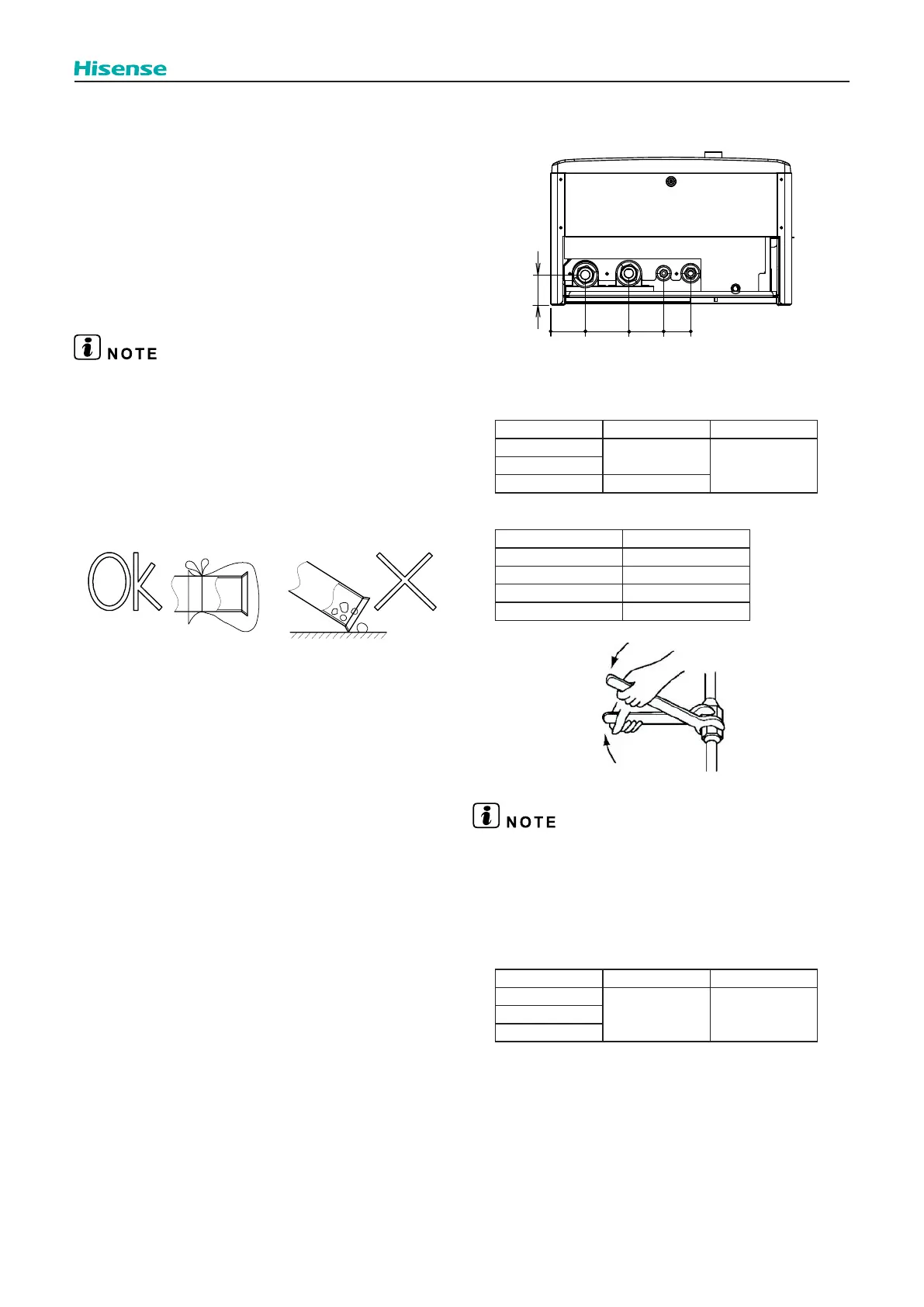
Location of Refrigerant and Water Pipeline are shown
below.
75
94
75
58
66
Water
inlet
Water
outlet
Gas
pipe
Liquid
pipe
8.1.7.2
REFRIGERANT PIPING CONNECTION
Piping connection size of indoor unit is shown below.
Model Gas pipe Liquid pipe
044(2.0HP)
Ø 12.7 (1/2”)
Ø 6.35 (1/4”)060(2.5HP)
080(3.0HP) Ø 15.88 (5/8”)
Torque required is shown below.
Pipe Diameter Torque(N•m)
Ø 6.35 14~18
Ø 9.53 33~42
Ø 12.7 50~62
Ø 15.88 63~77
Screw up the nut cap by two wrenches. Heat preservation material
on site should be used to prevent heat leakage of gas pipe, liquid
pipe and connecting nut cap.
8.1.7.3
WATER PIPING CONNECTION
(1) Piping connection size of indoor unit.
Model Gas pipe Liquid pipe
044(2.0HP)
G1” (male) G1” (male)060(2.5HP)
080(3.0HP)