267
Control function
10.8.2 Water pump control during DHW and SWP
10.8.2.1
Hydraulic separator is Enabled
WP1 and WP3 need to work together to deliver water circulation When hydraulic separator is Enabled ([hsb] set as
[Enabled]).
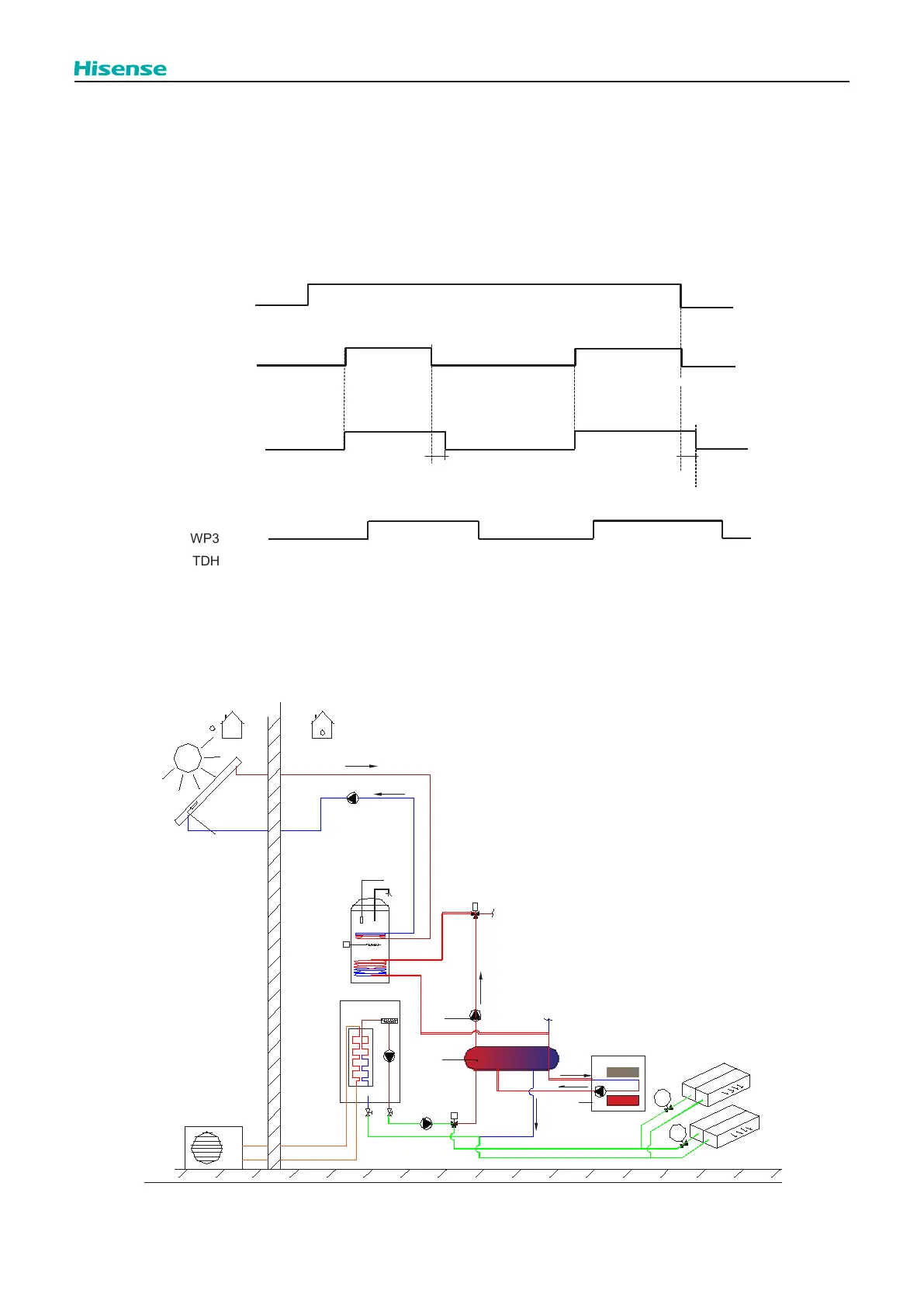
Water pump of WP1/WP3 works as shown in the graphic below:
[Point of DHW & SWP] should set as [After Hydr S] which means Point of 3-way valve for DHW and 3-way valve for
swimming pool is after hydraulic separator. Refer to 10.1.
DHW operation
Switch
ON/OFF
Demand
ON/OFF
2min
WP1
ON
OFF
ON
OFF
ON
OFF
ON:TDHW<TDHWS And Tow3≧TDHW+2
2min
WP3
OFF:TDHW>TDHWS
or Tow3≦TDHW+1
NOTE:
1. It is possible to operate Space cooling (heat pump and WP1)and DHW (WP3 or boiler)simultaneously when hydraulic
separator is available (refer to 10.2.5), [DSW5-2] set as [OFF] and [Point of DHW & SWP] set as [After Hydr S] (refer to
10.1), in this situation cooling water circulation will not pass through hydraulic separator. Boiler can work to meet DHW
demand, refer to 10.6.3 (7). In this situation WP1 works in space cooling referring to 10.8.1.1.1. And WP3 works referring
to DHW operation chart.
O
utdoor Unit
Solar Panel
D HW Tank
T
DHW
D HW EH
Solar Pump
Indoor Unit
AEH
T
solar
3w v C ooling
T iw
T ow
3wv DHW
Boiler
signal
T ow3
W P3
W P1
W P1
H ydr aulic Sep ara tor
F an Coil
cycle_1_room_1
cycle_1_room_2
ACT1
ACT2
2. WP1 is always OFF when Boiler works as replacement source and heat pump stop working in Emergency operation
(referring to 10.1.3.2), HP Block operation (referring to10.9.5) or Boiler working mode of [Alternative] (referring to 10.6.).