238
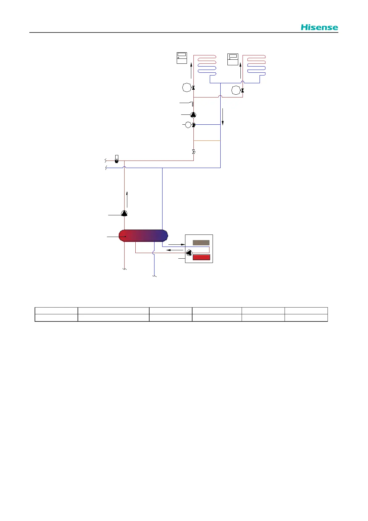
Control function
WP2
T ow2
M
Boiler
signal
T ow3
WP3
Vmix
Wired1
Wired2
cycle_2_room_1
cycle_2_room_2
H ydraulic Separator
3wv DHW
ACT3
ACT4
The conguration of this option should be done through the master controller.
Conguration →Complementary Heating →Boiler
Mark Description Default Value Range Steps Units
hsb Hydraulic Separator Status Disabled Disabled / Enabled
NOTE
:
1. When hydraulic separator is Enabled ,Auxiliary sensor on PCB1 of indoor unit must be congured as function of [Tow3]
and water sensor [Tow3] must be embedded in hot water side of hydraulic separator to detect hot water temperature
from the hydraulic separator. Refer to 10.10.
2. When hydraulic separator is Enabled, Optional Output signal need be congured as function of [WP3 ].and Additional
water pump [WP3] must be activated by [WP3 ] Output signal. This Output signal can be used as relay signal to wp3.
Refer to10.10.
3. When hydraulic separator is Enabled and water sensor (Tow3) is available, Tow3 is used to achieve Thermo ON/OFF
and capacity control (referring to 10.2.2.3 and 10.2.3.3) instead of [Tow].
4. Hydraulic separator is not recommended with big water volume (less than 25L) when DHW is combined in the system,
that will cause less eciency and additional heating time to heat up DHW tank.