316
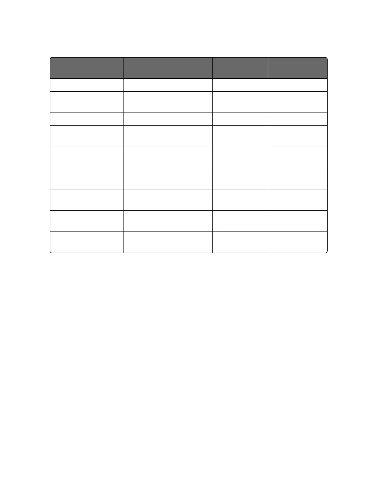
Register Numbers
(Dec)
Name Access Notes
SUPPORTED Point
2 Attribute NOT
SUPPORTED
1 = Read Only,
2 = Read/Write
3 Value (float high word) Read / Write
4 Value (float low word) NOT
SUPPORTED
5 Low Range (float high
word)
NOT
SUPPORTED
6 Low Range (float low
word)
NOT
SUPPORTED
7 High Range (float high
word)
NOT
SUPPORTED
8 High Range (float low
word)
NOT
SUPPORTED
9 to 13 Description Text (ASCII
string)
NOT
SUPPORTED
Register Count
The register count depends on the data format of the registers being
read or written.
Integer data is represented in sixteen bits and is transferred high
byte first.
Floating point data is transferred in IEEE 32-bit format.
The register count definitions are:
0001 = Integer Data
0002 = Floating Point Data
Chapter 11 - Modbus RTU Function Codes 20&21

 Loading...