234
Milliamperes
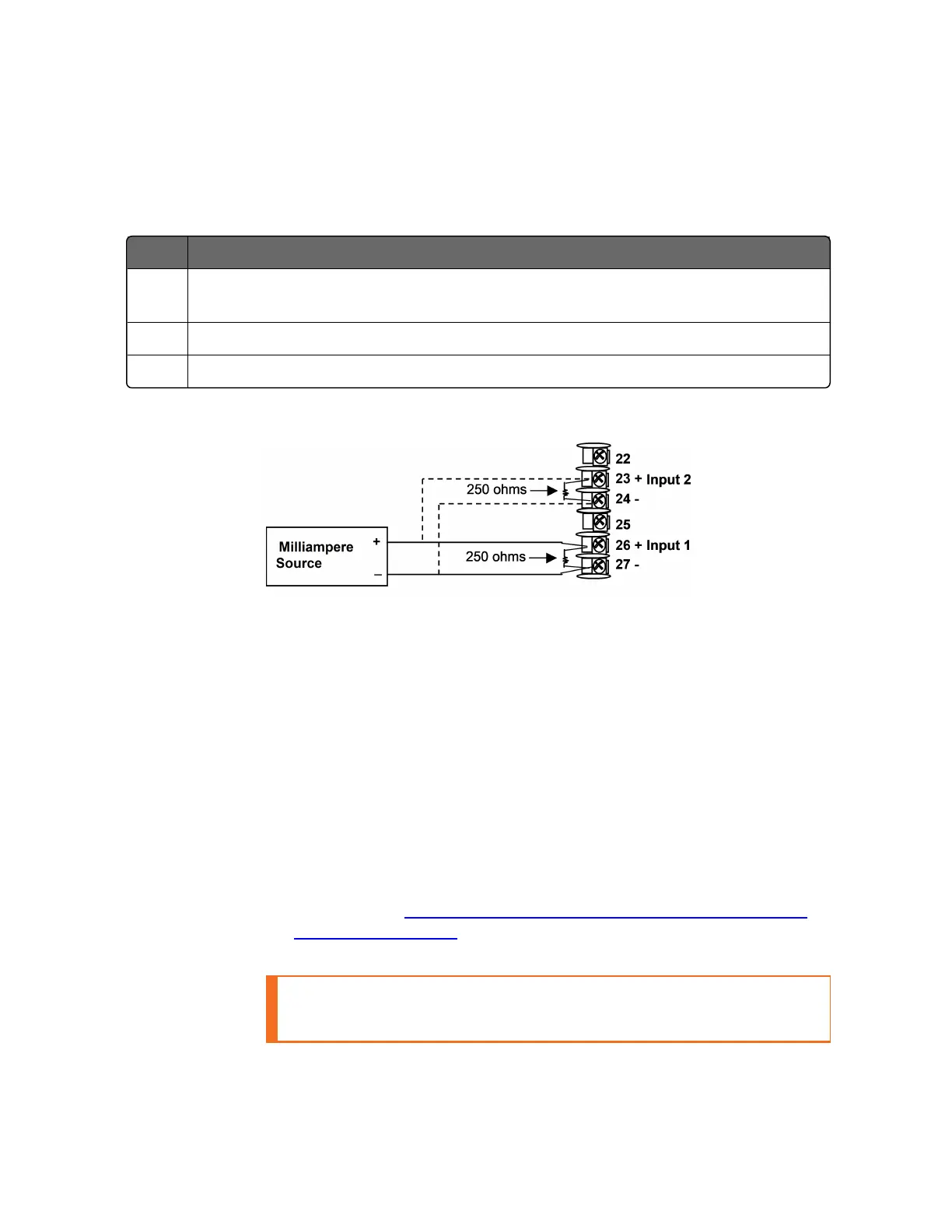
Table 6-6: Set Up Wiring Procedure for Milliampere Inputs
Step Action
1 Connect the copper leads from the calibrator to the Input #1 terminals as
shown in Figure "Wiring Connections for 0 to 20 mA or 4 to 20 mA Inputs".
2 Place current source at zero before switching on.
3 Do not switch current source ON/OFF while connected to the instrument.
Figure 6-5: Wiring Connections for 0 to 20 mA or 4 to 20 mA Inputs
Input 1 or 2 Calibration Procedure
Preliminary Steps
n
Apply power and allow the controller to warm up for 30 minutes
before you calibrate.
n
Before beginning the procedure, see Input 1 or 2 Set Up Wiring
for more information.
n
Make sure you have set Lock to NONE in the Security set up
group. See Security Set Up Group for more information.
n
See the table Voltage, Milliamp and Resistance Equivalents for
Input Range Values for Voltage vs. Resistance equivalents or 0 %
and 100 % range values.
CAUTION: For linear inputs, avoid step changes in inputs. Vary
smoothly from initial value to final 100 % value.
Chapter 6 - Input Calibration

 Loading...


