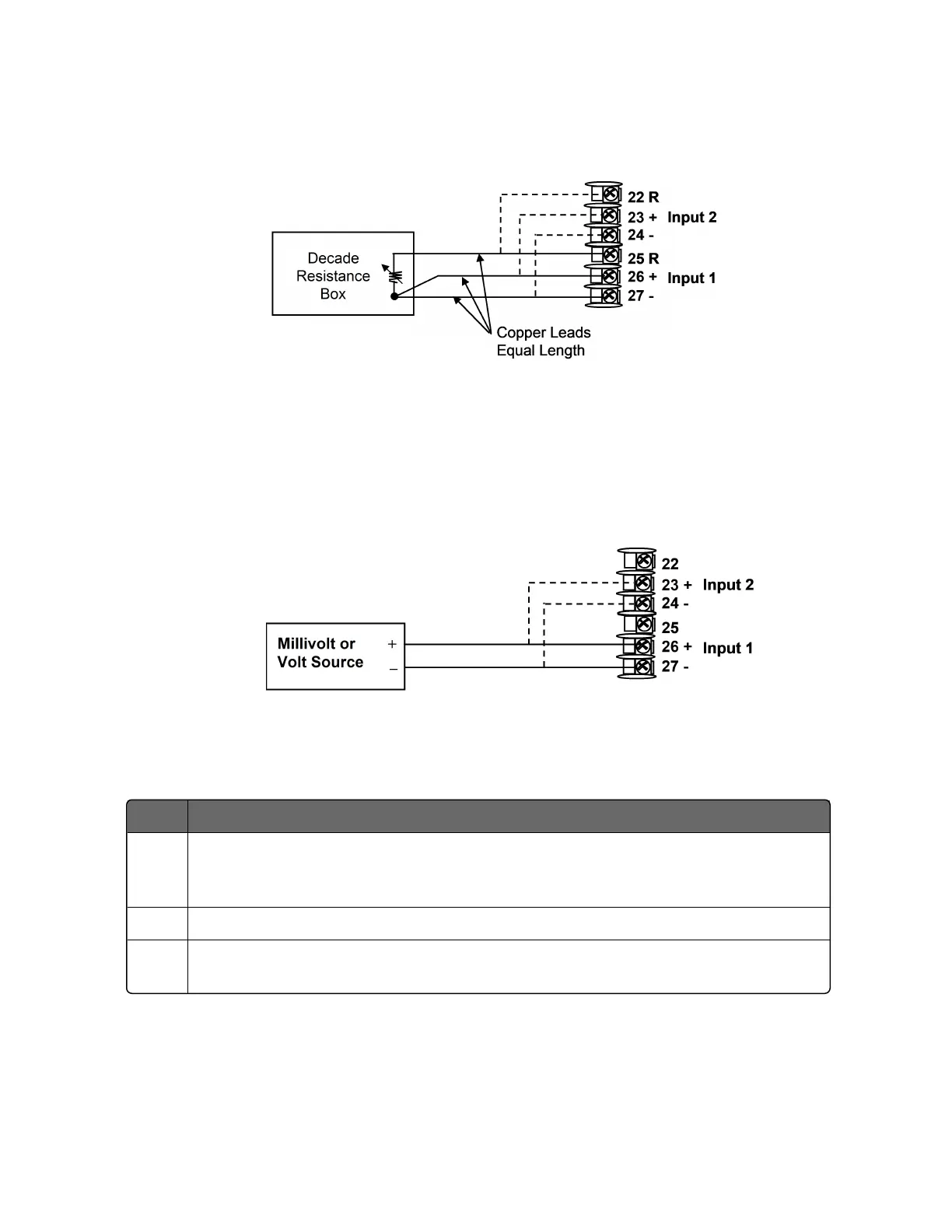
Figure 6-3: Wiring Connections for RTD (Resistance Thermometer
Device)
Millivolts, Volts or Thermocouple Differential Inputs
Refer to the following figure and wire the controller according to the
procedure given in the following table.
Figure 6-4: Wiring Connections for Thermocouple Differential,
Millivolts or Volts
Table 6-5: Set Up Wiring Procedure for Millivolts, Volts or Thermocouple Differential
Inputs
Step Action
1 Connect the copper leads from the calibrator to the Input #1 terminals as
shown in Figure "Wiring Connections for Thermocouple Differential, Millivolts
or Volts".
2 Place current/voltage source at zero before switching on.
3 Do not switch current/voltage source ON/OFF while connected to the
instrument.
233
Chapter 6 - Input Calibration

 Loading...


