Setpoints
You can use two separate local setpoints in the controller. The
identifying register addresses listed in the following table allow you
to select which setpoint you want to use and to enter a value in
Engineering Units (whichever is selected at register address 8D7
(Hex)) for that setpoint via communications.
Register Address
Make your selection using register address 8A5 (Hex) and enter the
value for the setpoint chosen using register address in table below.
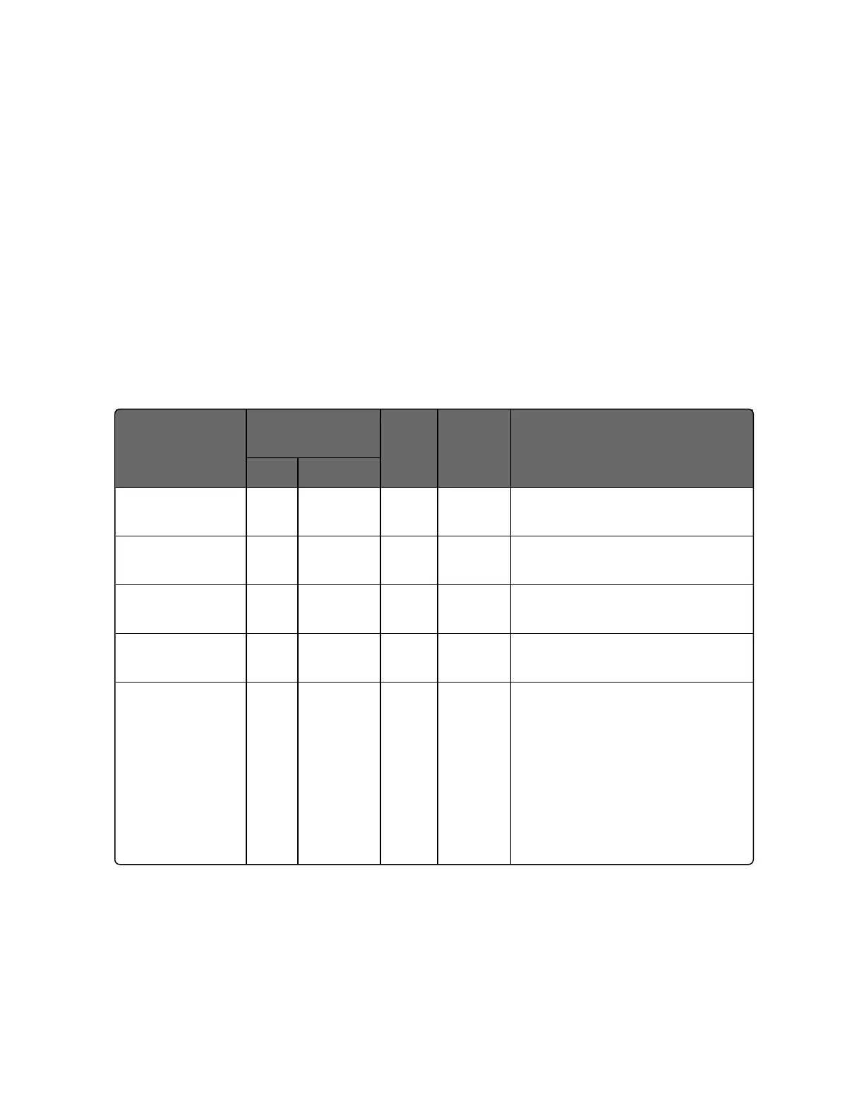
Table 11-10: Setpoint Code Selections
Parameter
Description
Register
Address
Data
Type
Access
Data Range or Enumerated
Selection
Hex Decimal
Local Setpoint
#1
123 291 FP R/W Value within the setpoint range
limits
Local Setpoint
#2
124 292 FP R/W Value within the setpoint range
limits
Local Setpoint
#3
125 293 FP R/W Value within the setpoint range
limits
Local Setpoint
#4
126 294 FP R/W Value within the setpoint range
limits
Number of
Local Setpoints
8A5 2213 INT R/W 00 = Local Setpoint #1 only
01 = 2nd Local Setpoint via
keyboard or communications
02 = 3rd Local Setpoint via
keyboard or communications
03 = 4th Local Setpoint via
keyboard or communications
327
Chapter 11 - Modbus RTU Function Codes 20&21
 Loading...


