228
Minimum and Maximum Range Values
Select the Range Values
Calibrate the controller for the minimum (0 %) and maximum
(100%) range values of your particular input type. Two input
controllers will need to have each input calibrated separately.
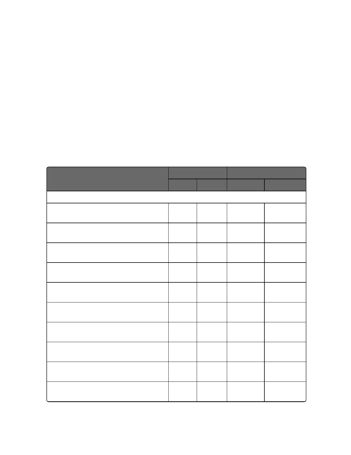
Select the Voltage, Current or Resistance equivalents for 0 % and
100 % range values from table below. Use these values when
calibrating your controller.
Table 6-1: Voltage, Milliamp and Resistance Equivalents for Input Range Values
Sensor Type
PV Input Range Range Values
°F °C 0% 100%
Thermocouples (per ITS-90)
TC B 0 to
3300
–18 to
1816
–0.100 mV 13.769 mV
TC E High –454 to
1832
–270 to
1000
–9.835 mV 76.373 mV
TC E Low -200 to
1100
-129 to
593
–6.472 mV 44.555 mV
TC J High 0 to
1600
–18 to
871
–0.886 mV 50.060 mV
TC J Mid 20 to
900
–7 to
482
– 0.334
mV
26.400 mV
TC J Low 20 to
550
–7 to
288
–0.334 mV 15.650 mV
TC K High 0 to
2400
–18 to
1316
–0.692 mV 52.952 mV
TC K Mid –20 to
1200
–29 to
649
–1.114 mV 26.978 mV
TC K Low –20 to
750
–29 to
399
–1.114 mV 16.350 mV
TC M High (Ni-Ni-Moly) 32 to
2500
0 to
1371
0.000 mV 71.773 mV
Chapter 6 - Input Calibration

 Loading...


