318
Reference Type Definitions
The Reference Type definition is always 06.
See Read Configuration Examples for more information.
File Number
The file number word contains the register number from Register
Address Structure. Although the register address structure tables
indicate up to 13 data registers are available for access, only register
address 3 is currently supported.
Register Address
The register address word represents the tag ID number for the
parameter(s) being accessed. The register address word is made up
of two bytes—the MSB = 00 always. The LSB contains the tag ID
number. The tag ID numbers represent the parameter’s register
address(es).See Configuration for more information.
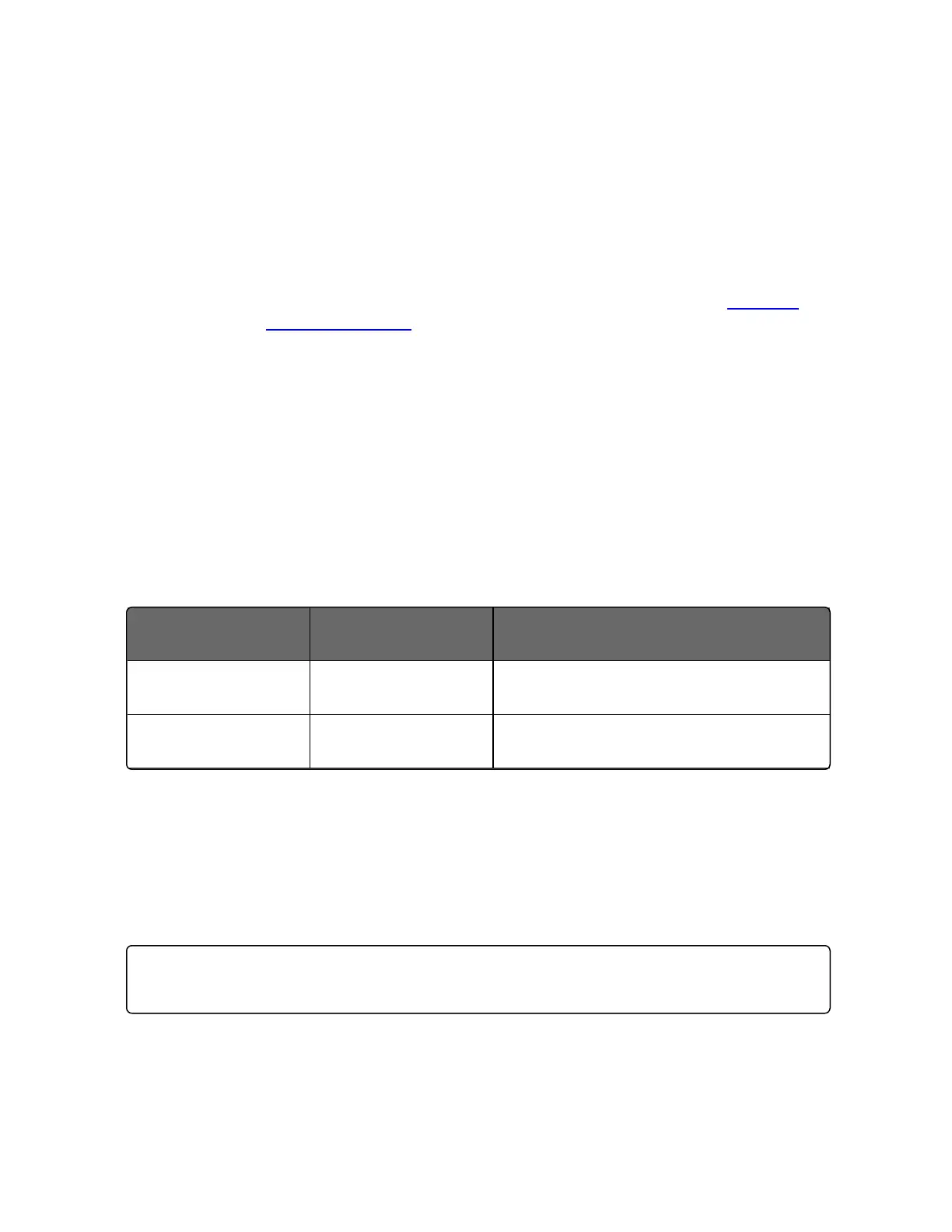
Table 11-4: Register Address Format for Function Code 20
Register Address(es)
(Decimal)
Register Address(es)
(Hex)
Format
1 to 2048 1 to 800 analog formatted data
(2 registers – IEEE 32-bit floating point)
2049 to 4096 801 to 1000 integer formatted data
(1 register – 16-bit integer)
Read Configuration Examples
Example #1
The following is an example of a request to read the Gain 1 value
using Function code 20.
Request Message (Read (Gain 1) = ID Tag
001)02 14 07 06 00 03 00 01 00 02 (CRC16)
Where:
02 = Address
Chapter 11 - Modbus RTU Function Codes 20&21

 Loading...


