EasyManuals Logo

Honeywell UDC2800 User Manual

Honeywell UDC2800
432 pages
To Next Page IconTo Next Page
To Previous Page IconTo Previous Page
Page #377 background imageLoading...
Page #377 background image
Digital Output Register Map
Use the identifying codes listed in the following table to read the
specific items.
A Write request for these codes will result in an Error message.
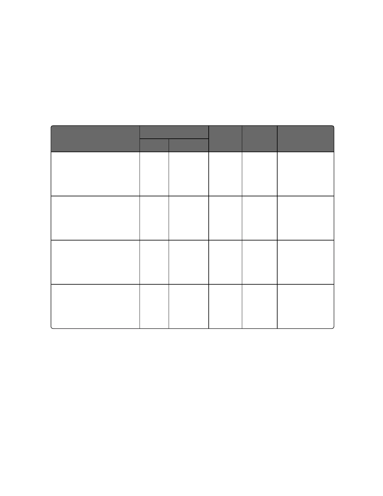
Table 12-3: Digital Output Parameters
Parameter Description
Register Address
Data
Type
Access Description
Hex Decimal
Output 1 0x00 1 Float R 0: No output
1: Hardware
channel Output
1
Output 2 0x01 2 INT16 R 0: No output
1: Hardware
channel Output
2
Alarm Relay 2 / Output 2 0x02 3 Coil R 0: No output
1: Hardware
channel Output
3
Alarm Relay 1 0x03 4 Coil R 0: No output
1: Hardware
channel Output
4
377
Chapter 12 - Standard Modbus Read, Write and Override Parameters

Table of Contents

Other manuals for Honeywell UDC2800

Questions and Answers:

Question and Answer IconNeed help?

Do you have a question about the Honeywell UDC2800 and is the answer not in the manual?

Honeywell UDC2800 Specifications

General IconGeneral
Control ModesPID, ON/OFF, Manual
MountingPanel Mount
DisplayDual 4-digit LED
Input TypesThermocouple, RTD, mA, mV, V
Output TypesRelay
Power Supply100-240 VAC, 50/60 Hz
CommunicationRS-485 Modbus RTU
Enclosure RatingNEMA 4X

Related product manuals