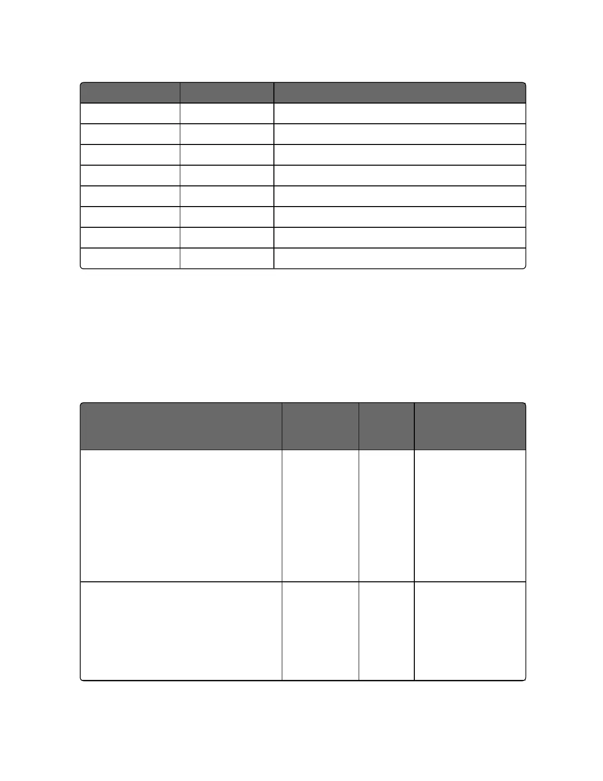
Start Address End Address Description
3600 3607 Set Point Programmer #8 Segment 1
3608 360F Set Point Programmer #8 Segment 2
3610 3617 Set Point Programmer #8 Segment 3
3618 361F Set Point Programmer #8 Segment 4
3620 3627 Set Point Programmer #8 Segment 5
3628 362F Set Point Programmer #8 Segment 6
3630 3637 Set Point Programmer #8 Segment 7
3638 363F Set Point Programmer #8 Segment 8
Segment Register Map
The table below describes the registers that are part of a setpoint
programmer segment. To determine the actual register address for a
parameter within a segment, add the register offset to the start
address of the segment.
Table 12-30: Segment Register Map
Parameter Name
Register
Offset within
Segment
Access Description
Ramp Segment 0 R Bit Packed
Bit 0:1 = ramp
segment; 0= soak
segment
Bit 1:1 = guaranteed
soak enabled; 0 =
guaranteed soak
disabled
Time or Rate 2
R/W Floating Point in
time units
configured for the
set point
programmer.
Writing to this
425
Chapter 12 - Standard Modbus Read, Write and Override Parameters

 Loading...


