54
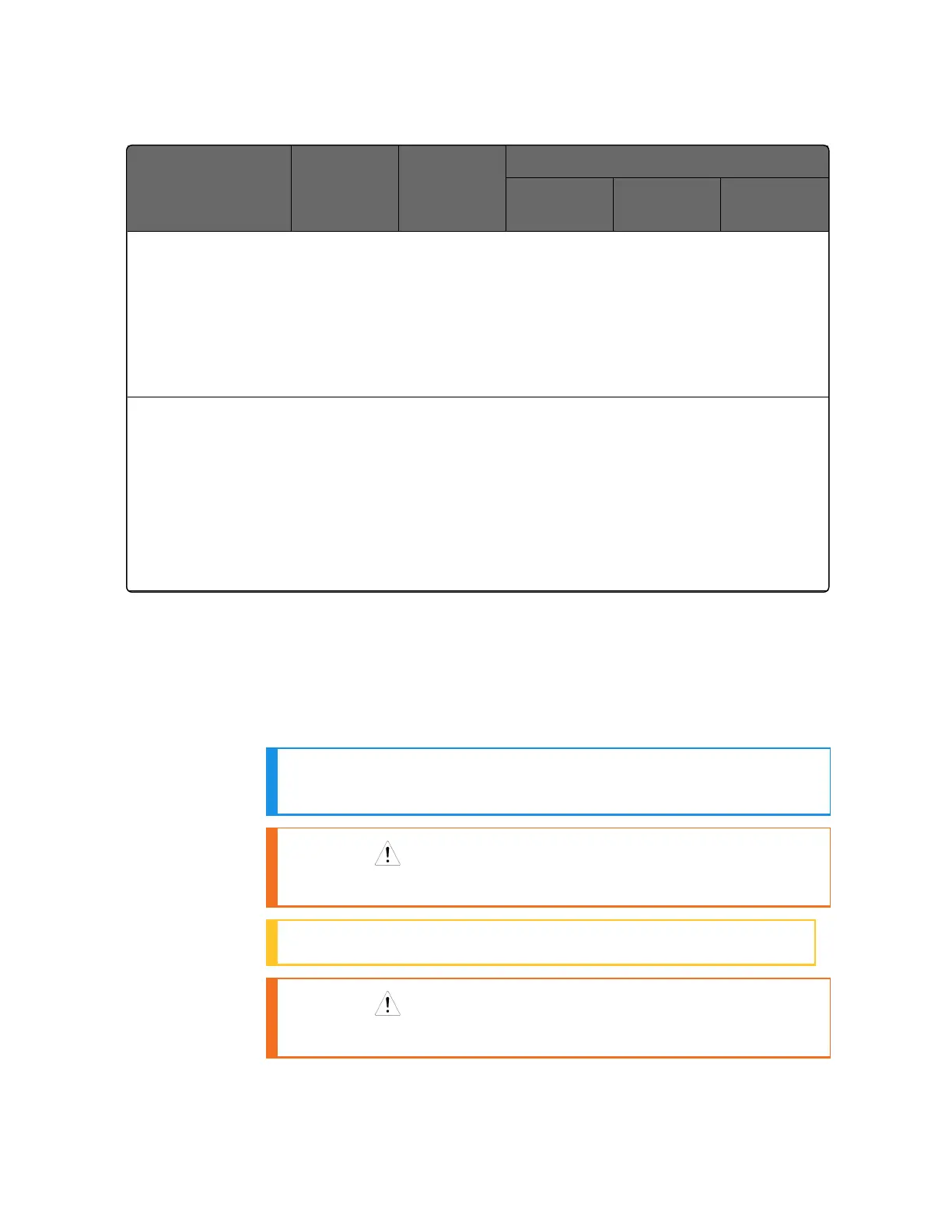
Output Algorithm
Type
Output 1/2
Option
Function of
Output 1/2
Function of Other Outputs
Output #3 Output #4
Auxiliary
Output
Output 1/2 option.
INU = Installed, Not Used – The installed Output 1/2 option is not used for the
configured output algorithm type.
Not Needed = Auxiliary Output is Not Needed to provide the desired output algorithm
and can be used for another purpose. With the proper configuration, Auxiliary Output
could also be used as a substitute for the Current Output.
Note 1: To obtain this output algorithm type with these Output 1/2 Options:
1) Configure the Out Algorithms selection as “Time Duplex”;
2) Configure Auxiliary Output for “Output” and;
3) Scale the Auxiliary Output as necessary for the desired output algorithm type.
For these selections, the Output 1 (HEAT) and Output 2 (COOL) signals will be present
both on the Auxiliary Output and on the two relays normally used for Time Duplex.
Wiring the Controller
Using the information contained in the model number, select the
appropriate wiring diagrams from the composite wiring diagram
below. Refer to the individual diagrams listed to wire the controller
according to your requirements.
NOTE: Torque screw assembly to 10 lb-inch (1.13 N•m) 27
places.
CAUTION: Use Copper Conductors Only for field-wiring
terminals.
ATTENTION: The wire gauge of terminal blocks is AWG 14~28.
CAUTION: Minimum temperature rating of the cable to be
connected to the field wiring terminals is 68 °C.
Chapter 3 - Installation
 Loading...


