EasyManuals Logo

Honeywell UDC2800 User Manual

Honeywell UDC2800
432 pages
To Next Page IconTo Next Page
To Previous Page IconTo Previous Page
Page #20 background imageLoading...
Page #20 background image
Operator Interface
Function of Displays
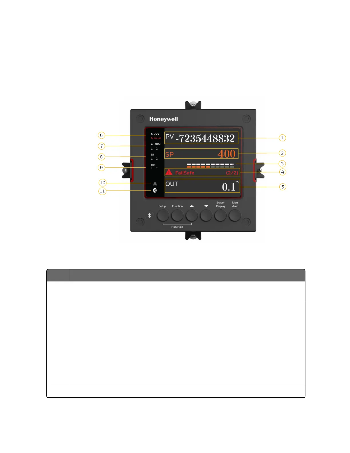
Figure 2-1: Function of Displays
Table 2-1: Function of Displays
Item Description
1 Upper display shows Process Variable value (maximum 10 digits including
decimal point, eg. -XXXX.X). Its unit can be F, C or none.
2 Middle display shows working Setpoint and its value (maximum 10 digits
including decimal point, eg. -XXXX.X).
SP = Local Setpoint 1
2SP = Local Setpoint 2
3SP = Local Setpoint 3
4SP = Local Setpoint 4
RSP = Remote Setpoint
3 Bar display shows Process Variable, Setpoint and Output from top to bottom in
20
Chapter 2 - Introduction

Table of Contents

Other manuals for Honeywell UDC2800

Questions and Answers:

Question and Answer IconNeed help?

Do you have a question about the Honeywell UDC2800 and is the answer not in the manual?

Honeywell UDC2800 Specifications

General IconGeneral
Control ModesPID, ON/OFF, Manual
MountingPanel Mount
DisplayDual 4-digit LED
Input TypesThermocouple, RTD, mA, mV, V
Output TypesRelay
Power Supply100-240 VAC, 50/60 Hz
CommunicationRS-485 Modbus RTU
Enclosure RatingNEMA 4X

Related product manuals