Permissible Wiring Bundling
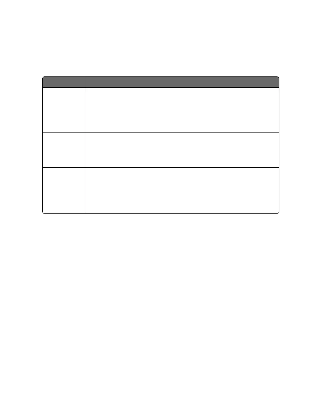
Table 3-5: Permissible Wiring Bundling
Bundle No. Wire Functions
1
l
Line power wiring
l
Earth ground wiring
l
Line voltage control relay output wiring
l
Line voltage alarm wiring
2 Analog signal wire, such as:
l
Input signal wire (thermocouple, 4 to 20 mA, etc.)
l
4-20 mA output signal wiring.
3 Digital input signals
l
Low voltage alarm relay output wiring
l
Low voltage wiring to solid state type control circuits
l
Low voltage wiring to open collector type control circuits
Wiring Diagrams
Identify Your Wiring Requirements
To determine the appropriate diagrams for wiring your controller,
refer to the model number interpretation in this section. The model
number of the controller is on the outside of the case.
Universal Output Functionality and Restrictions
Instruments with multiple outputs can be configured to perform a
variety of output types and alarms. For example, an instrument with
a current output and two relays can be configured to perform any of
the following:
1. Current Simplex with two alarm relays;
2. Current Duplex 100% with two alarm relays;
3. Time Simplex with one alarm relay;
51
Chapter 3 - Installation

 Loading...


