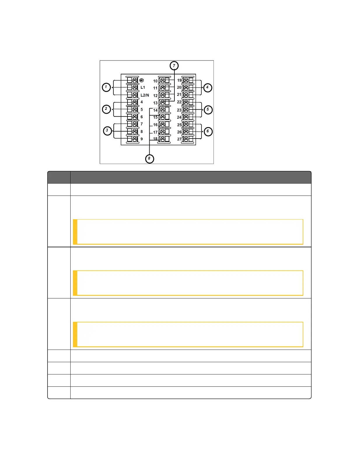
Figure 3-3: Composite Wiring Diagram
Item Description
1 AC/DC Line Voltage Terminals.
2 Output 3 Terminals (Output #2 or Alarm #2 in the Table I of UDC2800
Universal Digital Controller Model Selection Guide).
ATTENTION: If they are used as Relay Outputs, the wire gauge should be
AWG 14~22.
3 Output 4 Terminals (Alarm #1 in the Table I of UDC2800 Universal Digital
Controller Model Selection Guide).
ATTENTION: If they are used as Relay Outputs, the wire gauge should be
AWG 14~22.
4 Outputs 1 and 2 Terminals (Output #1 in the Table I of UDC2800 Universal
Digital Controller Model Selection Guide).
ATTENTION: If they are used as Relay Outputs, the wire gauge should be
AWG 14~22.
5 Input #2 Terminals.
6 Input #1 Terminals.
7 Aux. Output and Digital Inputs Terminals.
8 Communications Terminals.
55
Chapter 3 - Installation

 Loading...


