56
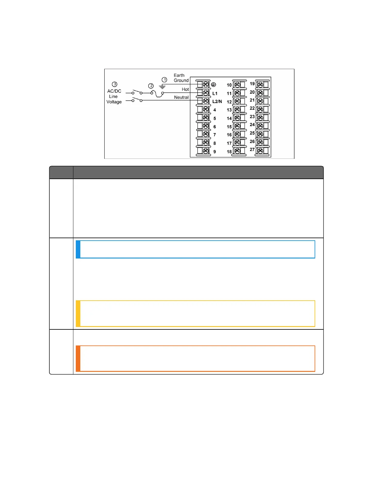
Figure 3-4: Mains Power Supply
Item Description
1 PROTECTIVE BONDING (grounding) of this controller and the enclosure in
which it is installed, shall be in accordance with National and local electrical
codes. To minimize electrical noise and transients that may adversely affect the
system, supplementary bonding of the controller enclosure to local ground
using a 14AWG ~ 20AWG copper conductor is recommended.
The wire gauge of power supply is AWG 14 (2.0 mm²) ~20 (0.5 mm²).
2
NOTE: It is only required for 90~264 Vac applications.
It is the user's responsibility to provide a switch and non-time delay (North
America), quick-acting, high breaking capacity, Type F (Europe), 1/2 A, 250 V
UL listed fuse(s), or 1 A UL listed circuit-breaker for 90-264 Vac applications,
as part of the installation.
ATTENTION: The nominal current of the switch must be larger than
fuse's related current.
3 The wire area of power supply is AWG 14 (2.0 mm²) ~20 (0.5 mm²).
CAUTION: Applying 90-264 Vac to an instrument rated for 24 Vac/dc
will severely damage the instrument and is a fire and smoke hazard.
Chapter 3 - Installation

 Loading...


