How to Set Up the Fractional-N Frequency Range
Adjustment
1. Remove the right-rear bumpers and right side cover. This exposes the
adjustment location in the sheet metal.
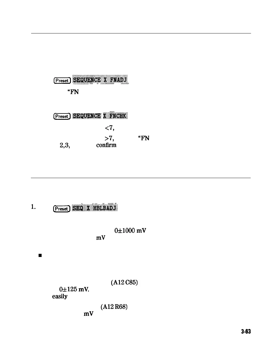
2. Press
(iGZ-j
~~~~~-.~..E~~~
(where X is the sequence number).
..~............................-::::
.::::
.:
-.......A
ii.. i.v.uA
.
.........
. . . . .
..A.......-.
3. Adjust the
“F’N
VCO TUNE” with a non-metallic tool so that the channel 1
marker is as many divisions above the reference line as the channel 2 marker
is below it.
. . . . . .
. . . . . .
’
:.............
4. Press
Ipreset]
?g#?jm@J
~.~@jK$&~
(where X is the sequence number).
n If the marker value is
~7,
you have completed this procedure.
n If the marker value is
>7,
readjust
“F’N
VCO TUNE” to 7. Then repeat
steps
2,3,
and 4 to
conlirm
that the channel 1 and channel 2 markers are
still above and below the reference line respectively.
How to Set Up the High/Low Band Transition
Adjustments
/
,.;
_
_
_
;
l.
Press
B
~~~~:~~~~~?~~~
(where X is the sequence number).
2. Observe the VCO tuning trace:
n If the left half of trace = of1000
mV
and right half of
trace = 100 to 200
mV
higher (one to two divisions): no adjustment is
necessary.
w
If the adjustment is necessary, follow these steps:
a. Remove the upper-rear bumpers and top cover, using a TORX
screwdriver.
b. Adjust the VCO tune (Al2
C85)
to position the left half of the trace
to
of125
mV.
This is a very sensitive adjustment where the trace could
easily
go off of the screen.
c. Adjust the HBLB
(Al2
R68)
to position the right half of the trace
125 to 175
mV
(about 1 to 1.5 divisions) higher than the left half.
Adjustments and Correction Constants
3-63