High/Low Band Transition Adjustment
&x&red
Equipment
and
9bols
Non-metalhc
Adjustment lb01 . . . . . . . . . . . . . . . . . . . . . . . . . . . . . . . . HP
P/N
8830-0024
Amlgzer
warmup time: 30 minutes.
This adjustment centers the VCO (voltage controlled oscillator) of the
Al2
reference assembly for high and low band operations.
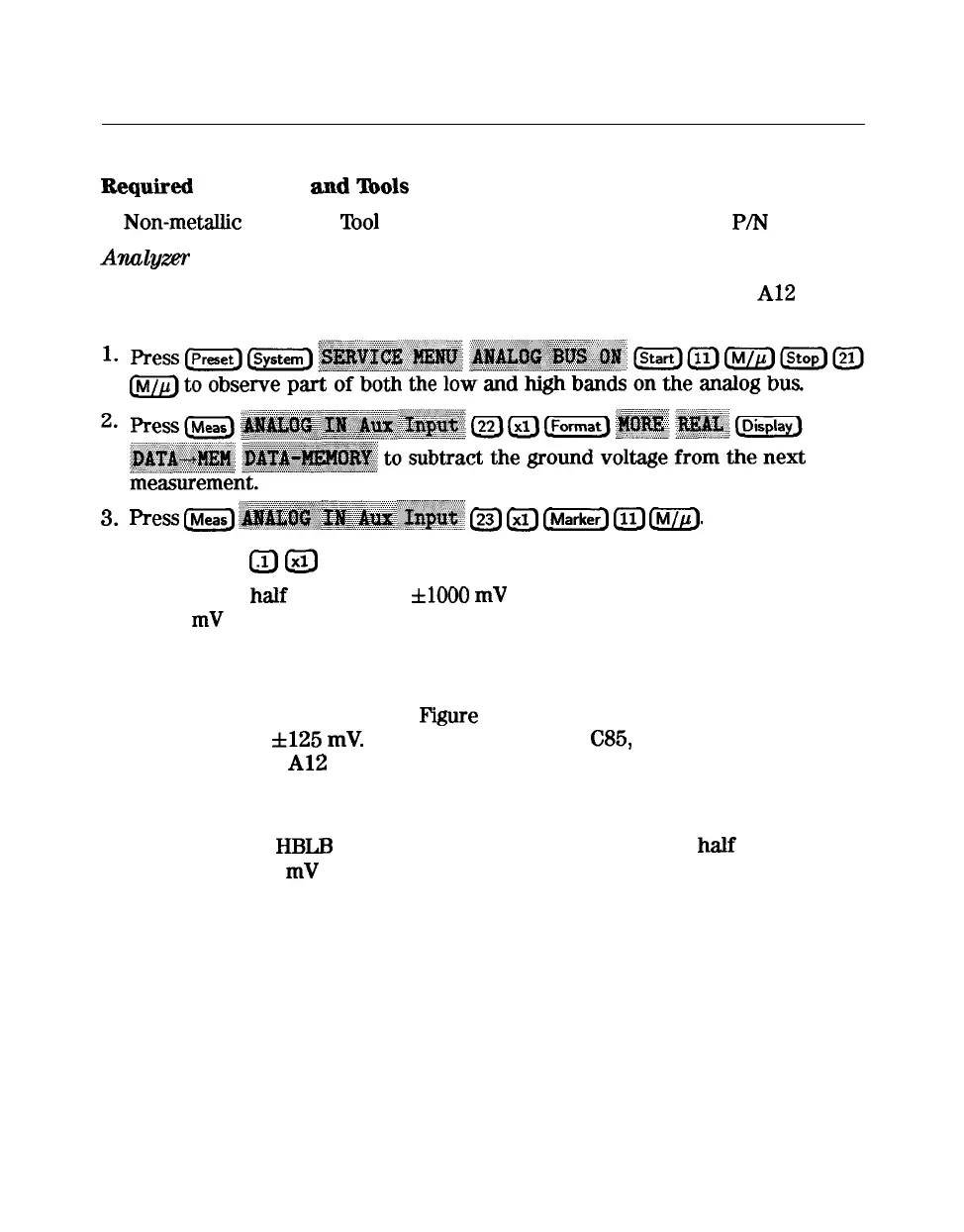
3.
Press
m
~~~~~~~~~~~~~~
(--&
a
(..,
Illl
@-&
4. Press (Scale
L.1]
Lxl_]
and observe the VCO tuning trace:
n If the left half of trace = 0
flOO0
mV
and right half of trace = 100 to
200
mV
higher (one to two divisions, see Figure 3-20): no adjustment is
necessary.
n
If the adjustment is necessary, follow these steps:
a. Adjust the VCO tune (see
Pigure
3-21) to position the left half of the
trace to 0
f125
mV.
The variable capacitor,
C85,
has a half-turn tuning
range if the
Al2
Reference Board is part number 08753-60209, and
seven turns if the part number is 08753-60357. Be careful not to
overtighten and damage the seven-turn capacitor.
b. Adjust the
HBLB
(see Figure 3-21) to position the right half of the trace
125 to 175
mV
(about 1 to 1.5 divisions) higher than the left half.
n Refer to Chapter 7, “Source Troubleshooting,” if you cannot perform the
adjustment.
3-52
Adjustments and Correction Constants