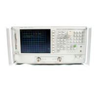
Line Power Module
The line power module includes the line power switch, voltage selector switch,
and main fuse. The line power switch is activated from the front panel. The
voltage selector switch, accessible at the rear panel, adapts the analyzer to local
line voltages of approximately 115 V or 230 V (with 350 VA maximum). The
main fuse, which protects the input side of the preregulator against drawing too
much line current, is also accessible at the rear panel. Refer to the
HP 8753E
Network
Anulgzer
lhstalhttin and Quick Start
Guide
for line voltage
tolerances and other power considerations.
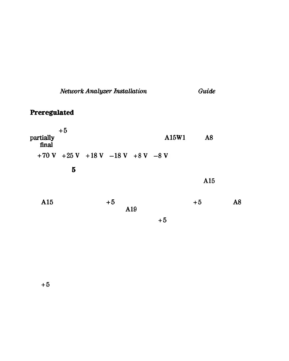
Preregulated Voltages
The switching preregulator converts the line voltage to several DC voltages. The
regulated
+5
V digital supply goes directly to the motherboard. The following
parGaIly
regulated voltages are routed through
A15Wl
to the A8 post regulator
for
llnal
regulation:
+7OV
+25V +18V
-18V
+8V
-8V
Regulated +
6
V Digital Supply
The + 5 VD supply is regulated by the control circuitry in the
Al5
preregulator.
It goes directly to the motherboard, and from there to all assemblies requiring
a low noise digital supply. A + 5 V sense line returns from the motherboard to
the
Al5
preregulator. The
+5
V CPU is derived from the
+5
VD in the A8 post
regulator and goes directly to the
A19
graphics system processor.
In order for the preregulator to function, the
+5
V digital supply must be
loaded by one or more assemblies, and the + 5 V sense line must be working. If
not, the other preregulated voltages will not be correct.
Shutdown Indications: the Green LED and Red LED
The green LED is on in normal operation. It is off when line power is not
connected, not switched on, or set too low, or if the line fuse has blown.
The red LED, which is off in
normal
operation, lights to indicate a fault in
the
+5
V supply. This may be an over/under line voltage, over line current,
or overtemperature condition. Refer to the troubleshooting chapters for more
information.
12-6 Theory of Operation

 Loading...


