2.
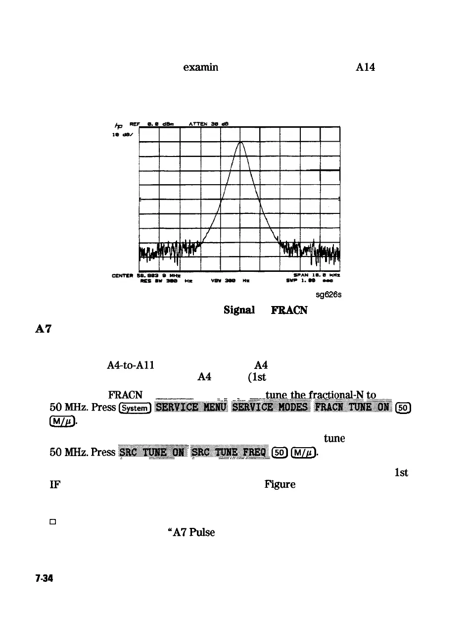
Use a spectrum analyzer, to
examin
e
the HI OUT signal from the
Al4
assembly. The signal should appear as clean as Figure 7-25. The comb shape
may vary from pulse generator to pulse generator.
sg626s
Figure 7-25. Stable HI OUT
Signal
in FRACN TUNE Mode
A7
Pulse Generator Check with Oscilloscope
Perform this check if a spectrum analyzer is not available.
1. Remove the
A4to-All
SMB cable from the A4 (R) sampler/mixer output.
Connect the oscilloscope to the A4 output
(1st
IF).
2. Activate the
FRACN
TUNE service mode and
t.~e,,ne.~~~~ion~~,~
t@-,
.._..................................
,.,,
_
. . . . . .
_
. . . . .
_
;...
_
_
. . .
i_
_
__.....i
. .
.,.
_
..;
..,.,
..,.,...
_.
,.
_
50
MHz.
press
Is-]
~~~~~~~~
~~~~~~~~~~
~~~:~,~~~~.~~~~
[sol
m-
3. Activate the SRC TUNE service mode of the analyzer and
tune
the source to
,::
7
.i
.:z:
.~~;.;~~~~;.~~~;~;;;~~;
ii
50
M&.
press
~~~~.~.~~~~~
~~~~~~~
L50)
Irln_llE).
i
. .
. . . . . . . . . . . . . . . . . . . . . . . . . . . . . . . . . . . . . . . . . . . . . . . . . . . . . .
_
._
_
_
_
. . . . . __
_
__ ____
_
.,.,.,.,.
i
_
_
,.,.
_.,._.,_.~.._
4. Set the SRC TUNE frequency to those listed in Table 7-7 and observe the
1st
Il?
waveforms. They should appear similar to
F’igure
7-26.
q
If the signals observed are proper, continue with “All Phase Lock Check”.
~3
If the signals observed are questionable, use a spectrum analyzer to
perform the preceding
“A7
Pulse
Generator Check with Spectrum
Analyzer”.
7-34
Source Troubleshooting