HP
8753E
NETWORK ANALYZER
-
PORT
1
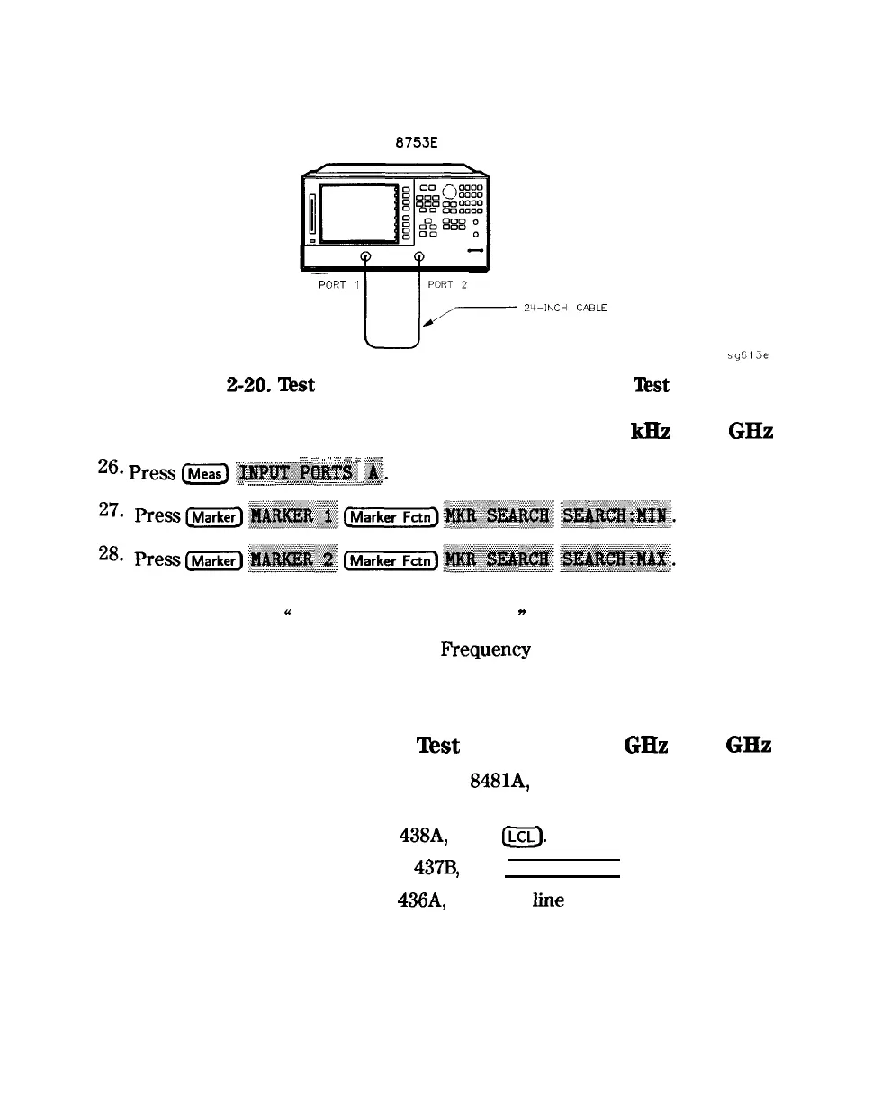
Figure
Z-20.
lkst
Port 1 Input Frequency Response
lkst
Setup
Test Port 1
Input
Frequency Response from 300
kHz
to 3
GHz
.::..
.::>.
,, ..
:::
<<
<<
:..zcg;
26.
Press
ideas)
~~~~~~~~~
jg.
.A....
..__.....
.::....
.
.
.
.
.
.
.
.
.A..
i
ii
T
..A_
.
.
.
.
.
.
.
.
.
.
.
.
.
.
.
..~.....~.~ .zv.%
ii.
29. Write the marker 1 or marker 2 reading, whichever has the larger absolute
magnitude, in the
U
Performance Test Record.
n
30. This completes the “Test Port Input
Frequency
Response” procedure if your
analyzer does not have Option 006. Otherwise continue with the next
sections
Power Meter Calibration for
Test
Port 2 from 3
GHz
to 6
GHz
31. Replace the power sensor with the HP
8481A,
and then setup the power
meter:
n If the power meter is an HP
438A,
press
a.
n If the power meter is an HP
437B,
press (PRESET/LOCAL].
n If the power meter is an HP
436A,
cycle the
iine
power.
32. Connect the equipment as shown in Figure 2-21.
System Verification and
249
Performance Tests