Al2
Reference Check
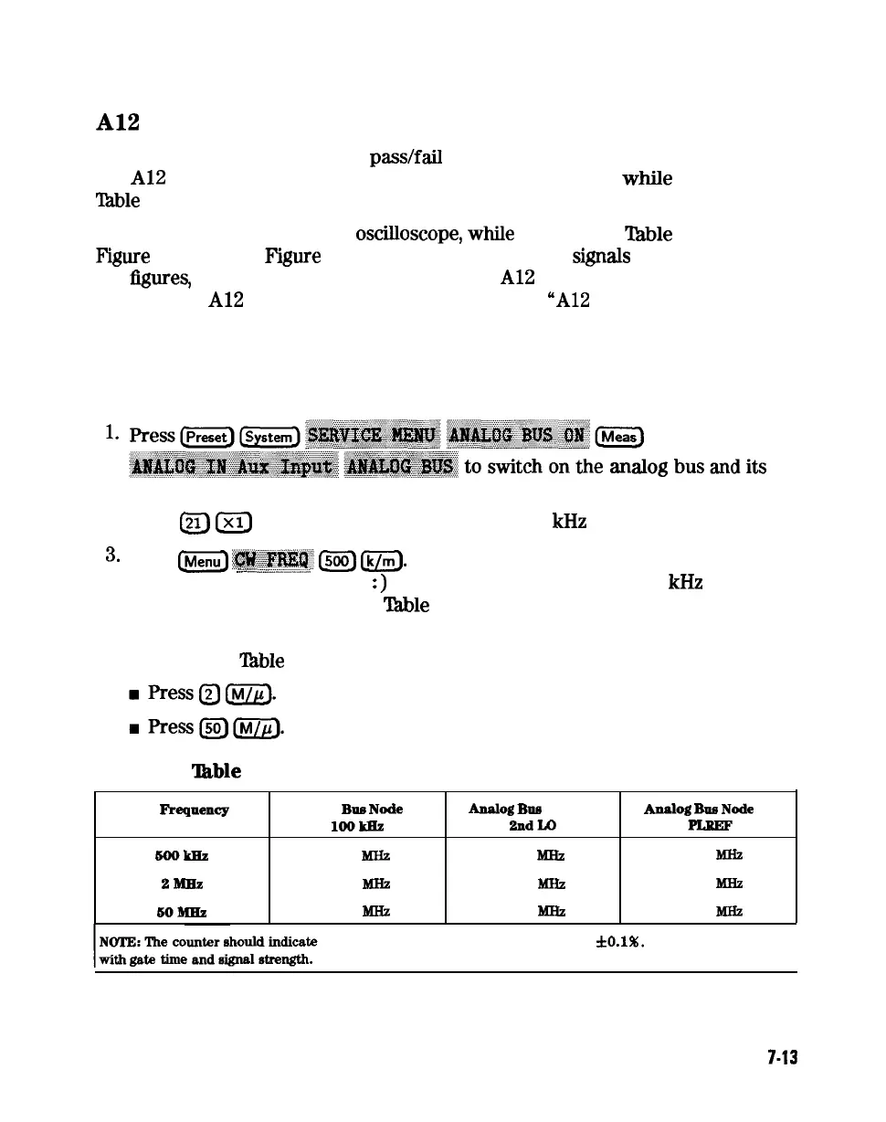
The signals are evaluated with
pass/fail
checks. The most efficient way to check
the
Al2
frequency reference signals is to use the analog bus while referring to
‘Pable
7-2.
Alternatively, you can use an
osciuoscope,
while
referring to
‘Ihble
7-3 and
Figure
7-8 through
F’igure
7-14. If any of the observed
signals
differs from
the
figures,
there is a 90% probability that the
Al2
assembly is faulty. Either
consider the
Al2
assembly defective or perform the
“A12
Digital Control Signals
Check”.
Both of these procedures are described ahead.
Analog Bus Method
counter.
2. Press
L21)
IXJ
to count the frequency of the 100
kHz
signal.
3.
Press
1Menu)
~~~~~~~
1500)
m.
Verify that the counter reading (displayed
:::
:...
ii
~........~...i__--.i
. . . . . .
on the analyzer next to cnt
:)
matches the corresponding 100
kHz
value for
the CW frequency. (Refer to
Table
7-2.)
4. Verify the remaining CW frequencies, comparing the counter reading with
the value in
‘Ihble
7-2:
able
7-2. Analog Bus Check of Reference Frequencies
CW
Fre4pency
5ookIiz
2Bm!&
6OBmz
Analog
BM
Node 21
Analog
BUE
Node 24
lOOkILt
2ndLO
0.100
MHZ
0.504
MHZ
0.100
MHZ
2.007
Jmz
0.100
MHZ
0.996
MB2
Analog
Bus
Node
25
0.500 MHZ
2.000 MHZ
1.000
Bmz
the frequencies listed in this table to within
3~0.1%.
Accuracy may vary
Source Troubleshooting
7-13
 Loading...


