Signal Separation
The
Built-In
I’kst
Set
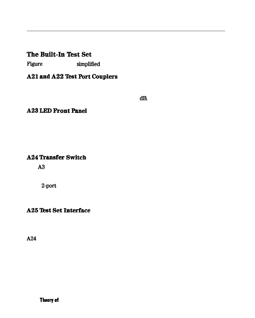
F’igure
12-9 shows a
simplified
block diagram of the analyzer’s built-in test set.
A21
and
A22
Test
Port
Cmplers
The analyzer’s test port couplers are used to separate signals incident to,
reflected from, and transmitted from the device under test. Each test port
coupler has a coupling coefficient factor of 16
dD.
A23
LED
kont
Panel
The LED front panel board indicates whether the source power is incident on
the analyzer’s test port 1 or test port
2.
The analyzer’s source power is directed
to test port 1 when making a forward transmission/reflection measurement.
Similarly, source power is incident at test port 2 when making a reverse
transmission/reflection measurement.
A24
Transfer
Switch
The A3 source output power is directed to either the analyzer’s test port 1 or
test port 2 via a low loss solid state transfer switch. With this switch, all four
S-parameters can be updated continuously (for example: the data obtained from
a full
2-port
calibration). In addition, the transfer switch provides termination
for the inactive test port in order to
minimize the crosstalk between the source
and receiver sampler.
A26
‘l&t
Set
Interface
The test set interface board provides biasing for active devices under test with
an external dc voltage. This dc voltage is applied directly to the test port center
pm. In addition, the test set interface board provides the drive signal for the
A24 forward/reverse transfer switch.
12-26
Theoryof
Operation