Receiver
Observe the A and B
Input
Traces
1.
2.
3.
4.
5.
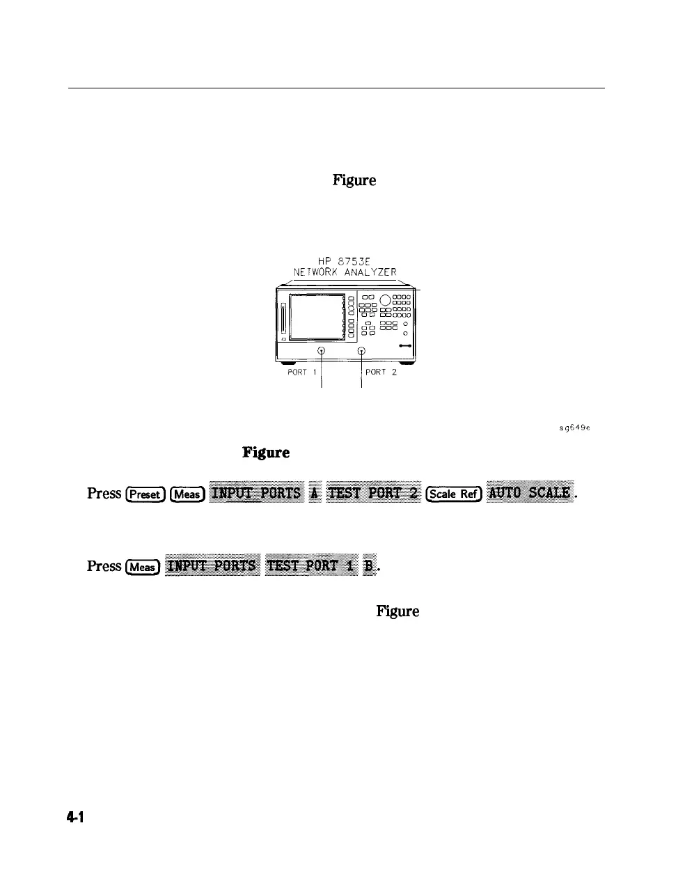
Connect the equipment as shown in
F’igure
47 below. Be sure that any
special accessories, such as limiters, have been disconnected. (The through
cable is HP part number 8120-4779.)
HP
8753E
NETWORK
ANALYZER
TEST PORT
THRU CABLE
sg649e
Figure
4-7. Equipment Setup
Observe the measurement trace displayed by the A input. The trace should
have about the same flatness as the trace in Figure 4-8.
Observe the measurement trace displayed by the B input. The trace should
have about the same flatness as the trace in
Figure
4-8.
4-l
6 Start Troubleshooting Here