Test
Port
Output
Worst
Case
2nd
Harmonic
l-
Press
(jjj
(jj)
.$$w
Ilo)
Ixl)
to set the test port power to + 10
dBm.
.::.i
2:
. . . . . ..i.
_.....
.:::.,
2. Press
m
(16)
a
@
@
Cc/n
to set the frequency range.
3.
Press
&iJ
~&$&&
@
Lxl]
to set the IF bandwidth to 10 Hz.
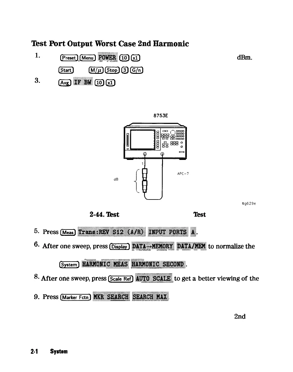
4. Connect the equipment as shown in Figure 2-44.
HP
8753E
NETWORK ANALYZER
PORT
1
1
PORT 2
20
CIB
FIXED
ATTENUATORS
CABLE
APC-7
24 INCH
s
g629e
Figure
Z-44.
‘l&t
Port Output Harmonics
‘lkst
Setup
6.
After
one
sweep,
press
~~~
~~~~~~~~~~~
~~~~~~~;
to
normalize
the
i”
i::::
._..
c:
_...
i.i
.
.._.............
ii
SW...
-
.._....._...
-
..__....
trace.
....
<.y:<<<<..
;,.:.:<
. . . . . .
p~.:~.:.:.:......,.:.:.:.:...
.::::y::::::::::::
y
.:.:.:.:.:.:.:.:.:.~:....:..~..:::::.
7. Press
&ZG)
~~~~~~~~:
~~~~~~~-..~~~~~~.
_
-
_....
.._.......__._.
-
__......_...__.....__
.,.
8.
After
one
sweep,
press
Cw-
:~~~~~~~~
to get a better
viewing
of the
,, ..,
,;;;
,,,,,,
.._...._.._.
-
_......._....
i...L....
trace.
g.
__...
..-
.._..._
-
_........
-
.._.
-
_...........
10. Write the marker 1 value (which appears on the analyzer display) on the
“Performance Test Record.” This is the worst case test port output
2nd
harmonic
2-l
02 System Verification and
Performance Tests