Analog In Menu
Select this menu to monitor voltage and frequency nodes, using the analog bus
and internal counter, as explained below.
lb
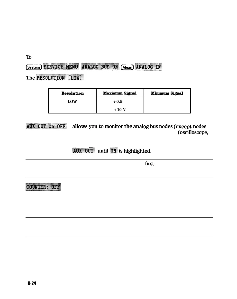
switch on the analog bus and access the analog in menu, press:
‘I’he
~~~~~,~~~~~~~~~~~
key
toggles
between
low and high resolution.
.,
R4%3OlIltiOIl
-SW
MiIlimnm8ignal
LOW
+0.5
v -0.5 v
HIGH
+lOV -10 v
~~~~~~~~~~~
&lows
you
to
monitor
the
adog
bus
nodes
(except
nodes
1, 2, 3, 4, 9, 10, 12) with external equipment
(osciIloscope,
voltmeter, etc). To do this, connect the equipment to the
AUX INPUT BNC connector on the rear panel, and press
_
-:..::;).,
. . . . . . . . . . . . . . . . . . . . . . . . . . . . . . . .
~~~~;~
,
stilly
is
highlighted.
_.._........
-
Caution
To prevent damage to the analyzer,
Ilrst
connect the signal to
the rear panel AUX INPUT, and then switch the function ON.
switches the internal counter off and removes the counter
display from the display. The counter can be switched on
with one of the next three keys. (Note: Using the counter
slows the sweep.) The counter bandwidth is 16 MHz unless
otherwise noted for a specific node.
Note
OUTPCNTR is the HP-IB command to output the counter’s
frequency data.
1 O-24
Service Key Menus and Error Messages