Receiver Theory
The receiver functional group consists of the following assemblies:
A4 sampler/mixer
A5 sampler/mixer
A6 sampler/mixer
A10 digital IF
These assemblies combine with the
A9
CPU (described in Digital Control Theory)
to measure and process input signals into digital information for display on the
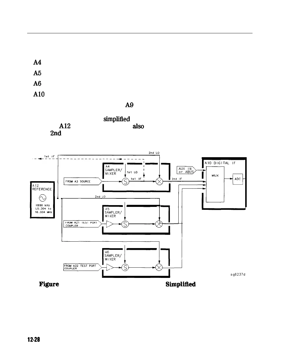
analyzer. Figure 12-10 is a
simplijied
block diagram of the receiver functional
group. The A12 reference assembly is
also
included in the illustration to show
how the 2nd LO signal is derived.
Figure 12-10. Receiver Functional Group,
Siiplilled
Block Diagram
12-28 Theory of Operation