\
30kHz
to
3
or
66HL
30kHr
to 3
or
MHZ
R
I
-
c
---a
-
SYNTHESIZED
TEST
RECE I VER
DISPLAY
SOURCE
SET
AC
piiq
El-
sg623Bd
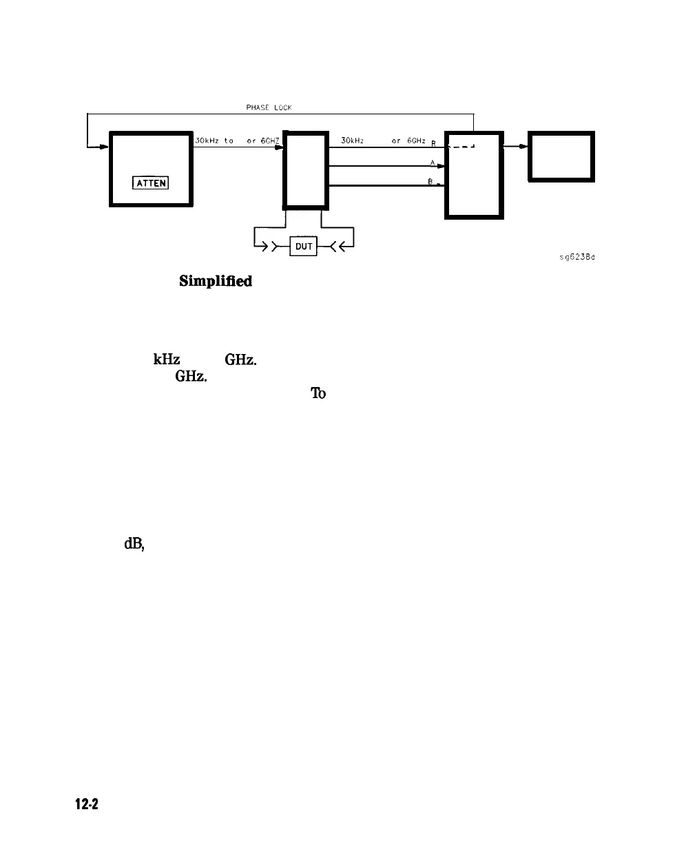
Figure 12-1.
Simplirred
Block Diagram of the Network Analyzer System
The Built-In Synthesized Source
The analyzer’s built-in synthesized source produces a swept RF signal in the
range of 30
kHz
to 3.0
GHz.
The HP 8753E Option 006 is able to generate
signals up to 6
GHz.
The source output power is leveled by an internal ALC
(automatic leveling control) circuit.
lb
achieve frequency accuracy and phase
measuring capability, the analyzer is phase locked to a highly stable crystal
oscillator.
For this purpose, a portion of the transmitted signal is routed to the R channel
input of the receiver, where it is sampled by the phase detection loop and fed
back to the source.
The Source Step Attenuator
The 70
dB,
electro-mechanical, step attenuator contained in the source has very
low loss. It is used to adjust the power level
to
the device under test without
changing the level of the incident power in the reference path. The user sets
the attenuation levels via the front panel softkeys.
12-2
Theory of Operation