Node 11 Aux Input (rear panel input)
.
.
.
.
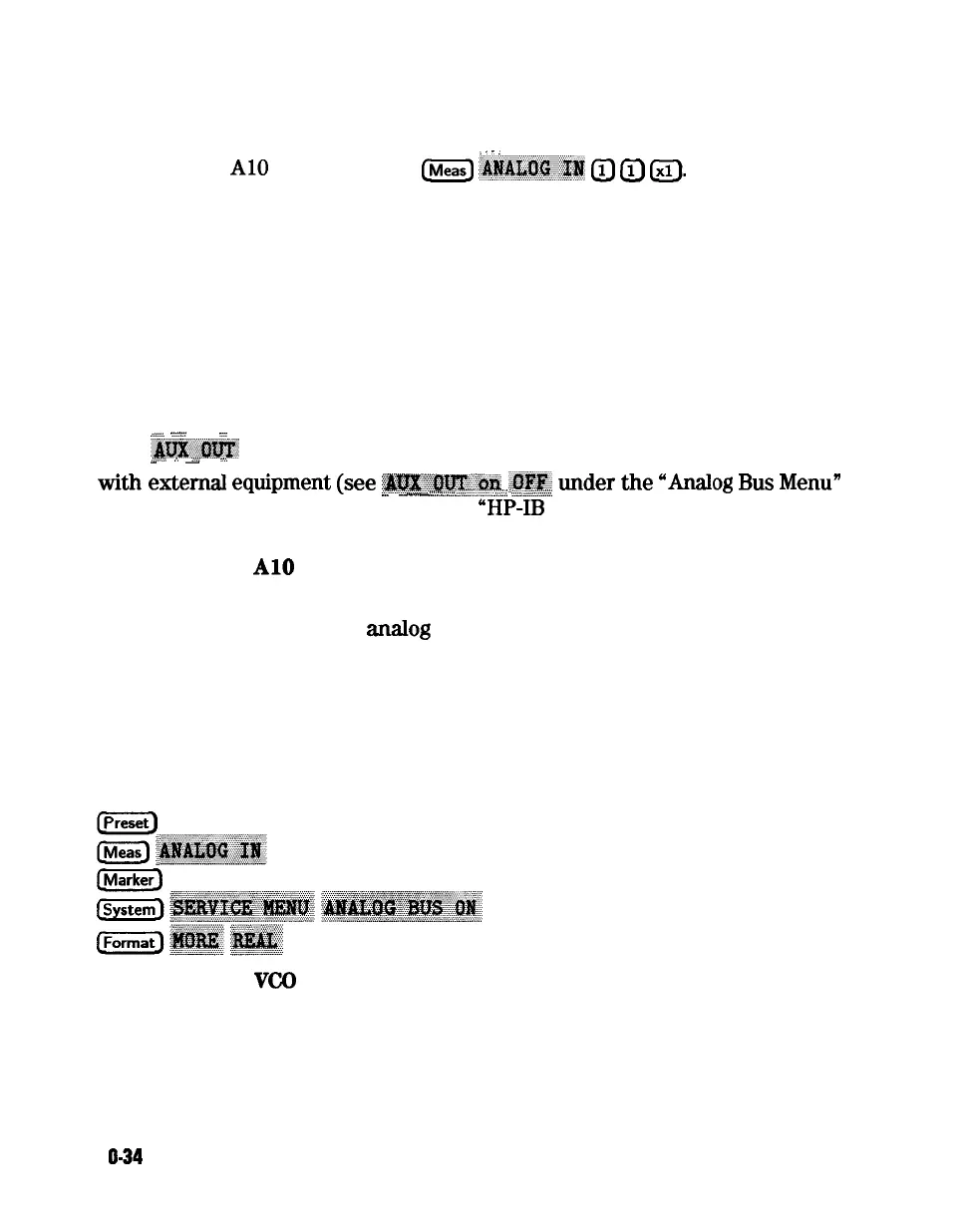
Perform step
A10
and then press
(Meas)
-#JAI,Zi$.@#
(iJ
(TJ
(ZJ.
This selects the rear panel AUX INPUT to drive the analog bus for voltage
and frequency measurements It can be used to look at test points within the
instrument, using the analyzer’s display as an oscilloscope. Connect the test
point of interest to the rear panel AUX INPUT BNC connector.
This feature can be useful if an oscilloscope is not available. Also, it can be used
for testing voltage-controlled devices by connecting the driving voltage of the
device under test to the AUX IN connector. Look at the driving voltage on one
display channel, while displaying the S-parameter response of the test device on
the other display channel.
_
_
. . .
. .
_
. .
With
.JKK&&%EY
switched ON, you can examine the analyzer’s analog bus nodes
,,.:.:::.
*
. .
::::
. . . . . . . . . . . . . . . . . . . . %.,.,
-
-
.
with
eaem&
equipment
(see
~~~~~‘~~~
&f$~;
under
the
“An&g
Bus
Menu”
-
.
-
._...
-
._........i.
1..........._.....
>..A.:
. . . .
.
<...s”:‘<.x<<<
heading). For HP-IB considerations, see
“HP-1B
Service Mnemonic Definitions,”
located later in this chapter.
Node
12
A10
Gnd (ground reference)
This node is used in the “Analog Bus Correction Constants” adjustment as a
reference for calibrating the
anaIog
bus low and high resolution circuitry.
All Phase Lock
To observe the All analog bus nodes, perform step All, below. Then follow the
node-specific instructions.
Step All.
Press:
Node 13
VCO
Tune 2 (not used)
1 O-34
Service Key Menus and Error Messages