7. For Option 006 Instruments Only: Zero and calibrate the power meter
ad
HP
8481A
power
sensor.
‘J’&n
press
~~~.~~~~~~:~~~~~~.~::~~;-
to
meate
. . . . . . . .
i
. . . . .
2x..
ii
~....~.~.~.~.~.~.~~
. . . .
.z
ii
.~................................
.._.
~.~.~::;
._.............
. . _
_...: i
a power sensor calibration table for power sensor B (HP
8481A),
using the
softkeys mentioned above.
Determine the Insertion Loss of the Cable at 1
GHz
9.
PressLcenter_)(TJ@FJ(3&J(%GJIM_U.
::::;:;::.
. .
;..+:>>;;>;.;,;,,
.;:
10.
Press
Ical]
~~~~~
~~~~.~~:~~~
~~~,
~~~~~~~~
~~~~~~~.
.._
;..;..>;.>A
. .
. . .
.:
i
. . . .
..s
.
. . . . . . . .
..-.......~...........~..........~_~~
.A..
. . . .
..A . . . . .
.
A...>.~~
ii.....
_.......
-
.._
-...-
_.._...._
~~~~-.:::..w.Le~.2
. . . . . . . . . . . .
.>.;..A
. . . . . . ..i
i
. . .
..A
.:::..-.::::
i_..~.G.~~~.i
. . . . . . . .
ii
:::.
in.......
.._......
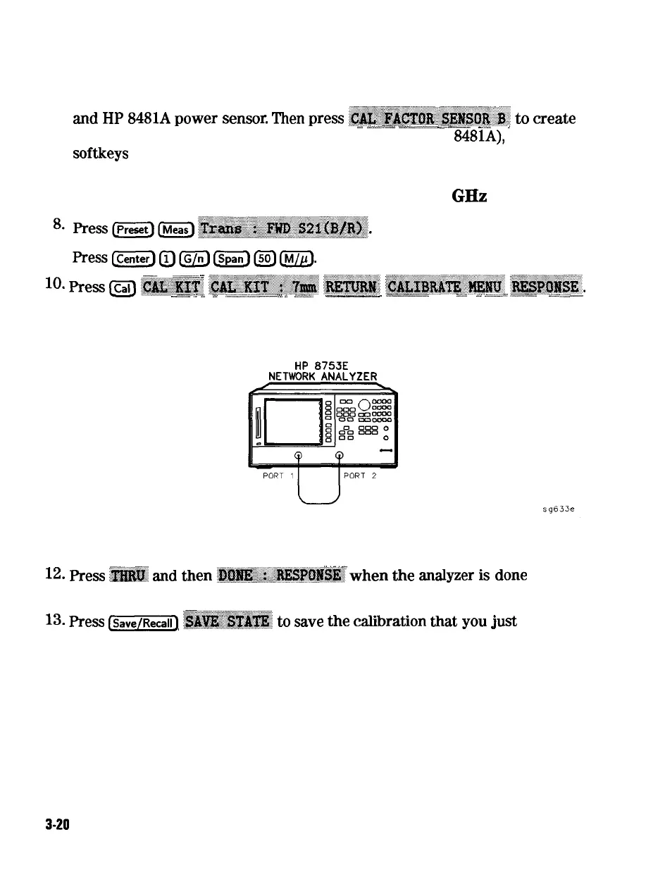
11. Connect the 24 inch cable from Port 1 to Port 2, as shown in Figure 3-3.
HP
8753E
NETWORK
ANALYZER
Figure 3-3. First Connections for Insertion Loss Measurement
_
,.
.,.
,.
_
12.
press
i$&$&..
and
then
:~~~~~~~~~~~~~~
when
the
analyzer
is
done
measuring the through.
_
. . . . . . . . . . . . . . . . . . .
13.
fiess
[W)
~~~~~~~~
to
Save
*e
calibration
aat
you
just
made.
14. Make the connections as shown in Figure 3-4.
3-20
Adjustments and Correction Constants