Troubleshooting When One or More Inputs Look Good
Since at least one input is good, all of the common receiver circuitry beyond the
multiplexer is functional. Only the status of the individual sampler/mixers and
their individual signal paths is undetermined.
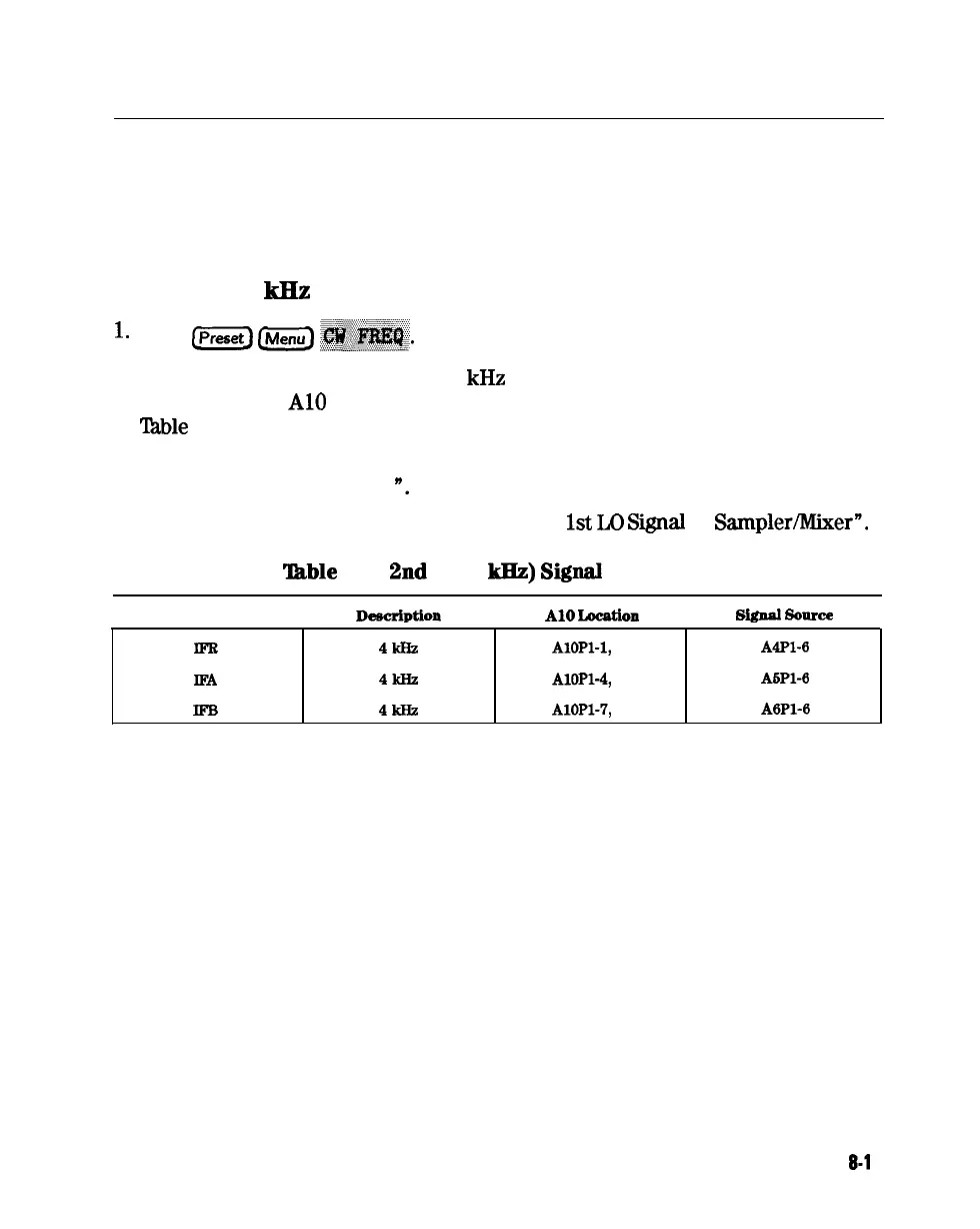
Check the 4
kHz
Signal
l-
Press
Lpreset)
LMenu)
~~~~~.
2. Use an oscilloscope to check the 4
kHz
output of the sampler/mixer in
question at the
Al0
assembly. The input and output access pins are listed in
lhble 8-2. The signal should resemble the waveform of Figure 8-6.
q
If the signal is good, continue with “Check the Trace with the Sampler
Correction Constants Off
n.
q
If the signal is bad, skip ahead to “Check
1st
Lo
SiiaI
at
Sampler/Mixer”.
‘ItLble
8-2.
2nd
IF (4
kHz)
Signal
Locations
I
Mnemonic
I
DeecrlPtlon
I
A10
Locatlou
I
slgual
solute
I
lm
IFA
IFB
4kHz
AlOPl-1,
31
A4Pl-6
4kHz
AlOPl-4,
34
ASPl-6
4kHz
AlOPl-7,
37
A6Pl-6
Receiver Troubleshooting
8-l
1