&T
REGULATOR
BOARD
SOLDER
s,
DE
::I:I:::
:
A1532
NOTE-
I
1
VOLTAGES
ALL
CABLES
AND
ASSEMBLIES
CONNECTED
sb6130d
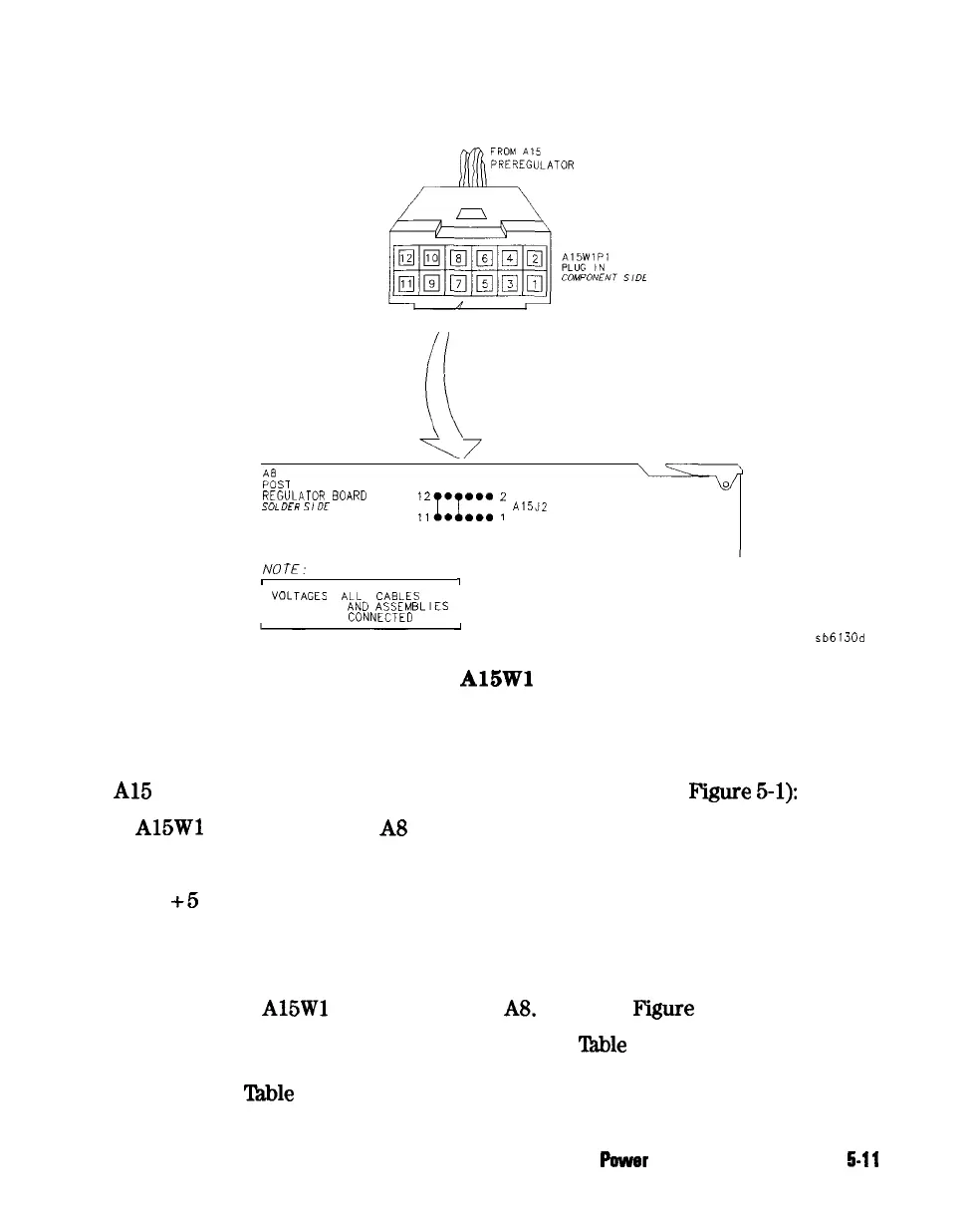
Figure 5-6.
A15Wl
Plug Detail
Check for a Faulty Assembly
This procedure checks for a faulty assembly that might be shutting down the
Al5
preregulator via one of the following lines (also refer to
F’igure
5-l):
n
A15Wl
connecting to the A8 post regulator
n
the + 5 VCPU line through the motherboard
n
the
+5
VDIG line through the motherboard
Do the following:
1. Switch off the analyzer.
2. Ensure that
A15Wl
is reconnected to
A8.
(Refer to
Figure
5-5.)
3.
Remove or disconnect the assemblies listed in
‘lhble
5-3 one at a time
and in the order shown. The assemblies are sorted from most to least
accessible.
Table
5-3 also lists any associated assemblies that are supplied
Puwer
Supply Troubleshooting
5-11