by the assembly that is being removed. After each assembly is removed or
disconnected switch on the analyzer and observe the red LED on
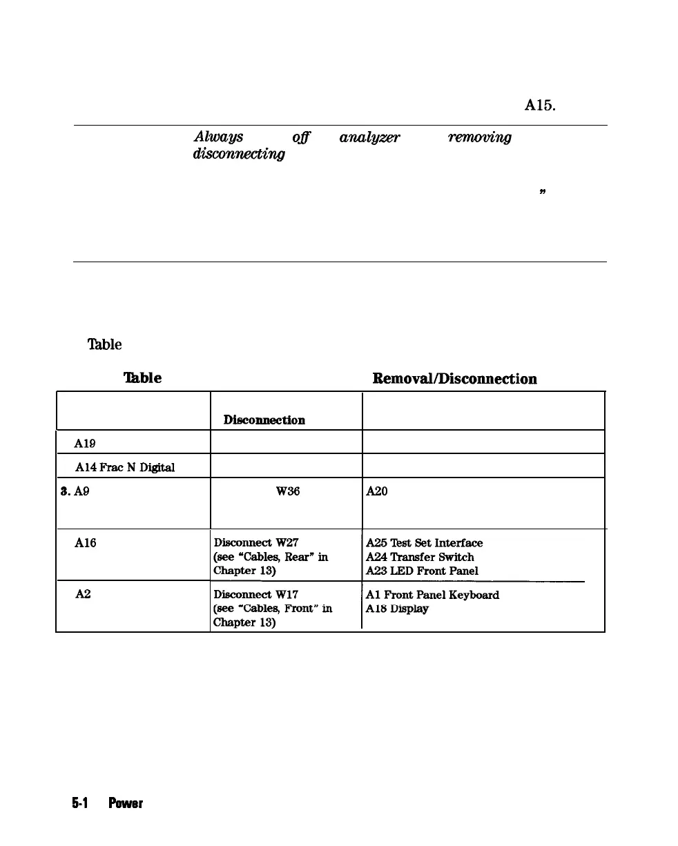
A15.
Note
n
Alwags
switch
ofl
the
analgzer
before
rewwwing
or
disconnecting assemblies.
n
When extensive disassembly is required, refer to Chapter 14,
“Assembly Replacement and Post-Repair Procedures.
n
n
Refer to Chapter 13, “Replaceable Parts,” to identify specific
cables and assemblies that are not shown in this chapter.
q
If the red LED goes out, the particular assembly (or one receiving power from
it) that allows it to go out is faulty.
q
If the red LED is still on after you have checked all of the assemblies listed in
‘lhble
5-3, continue to “Check the Operating Temperature”.
‘able
5-3. Recommended Order for
RemovaUDisconnection
Assembly
Removal or Other Assemblies that Receive
To Remove
Disconne&ion
Method
Power from the Removed Assembly
1.
A19
Graphics Processor
Remove from Card Cage None
2.
A14PracNDigital
Remove from Card Cage None
3.
A9
CPU
Disconnect
W36
A20 Disk Drive
(see “Cables, Rear” in
Chapter 13)
4.
Al6
Rear Panel Interface
5. A2 Front Panel Interface
5-l
2
Power
Supply Troubleshooting