10. Write the marker 1 value (which appears on the analyzer display) on the
“Performance Test Record.
n
This is the worst case test port output
2nd
harmonic
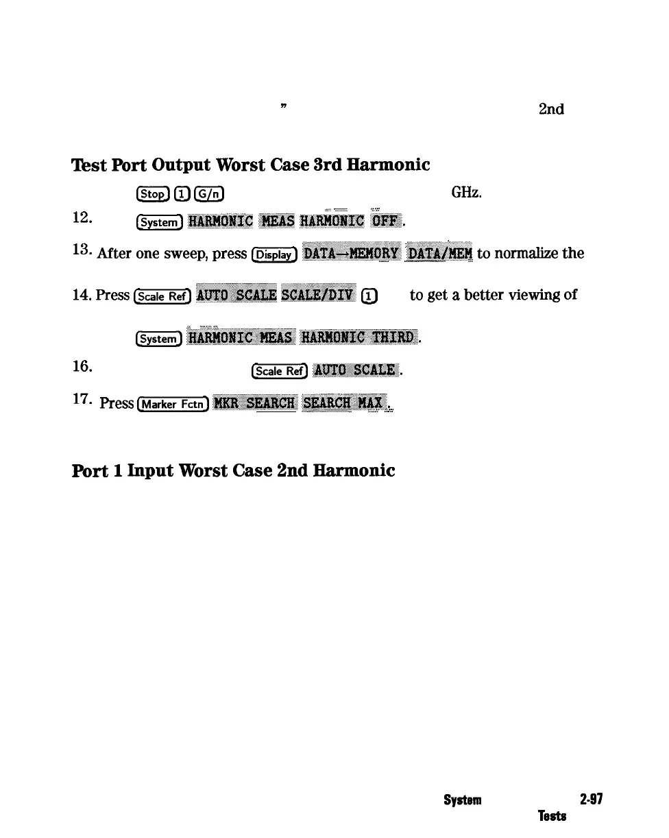
Test
Port
Output
Worst
Case
3rd
Harmonic
11. Press
@
0
@JJ
to change the stop frequency to 1
GHz.
_
.,
_
. . . . . . . . . . . . . . . . . . . . .
.,.,
.,.:
12.
Press
@iiG)
lfi&JfQggQ
i#Ei&
lQk!B!~~~E
lI&!j@~.
,...
.,..,
,.
i
13.
After
one
sweep,
press
@j@
‘~~~~~~~~~.
&&&&f@f
to
nom&e
the
..__.................~......
/i
.._...
trace.
.*.....
)i
14.
Press
Is-=
~~~~~
~~~~~~
@
(xl) to
get
a
better
viewing
of
the trace.
i
. . . . . . . . . . .
..I
..;;:. :.:.
15.
Press
@ZE)
~~~~~~~~~
~~~~~~.~~~.
16.
After one sweep, press
&XT@
~~~~~~~~.
17.
press
(m)
~~~~
‘~~:~~~~.
.._
_~...............................i
i
. . . . . . . . . . . . . . . . . .
..~.
ii . . . . . . .
_
..:..
18. Write the marker 1 value on the “Performance Test Record.”
Port
1
Input
Worst
Case
2nd
Harmonic
19. Connect the equipment as shown in Figure 2-43.
System
Verification and
247
Performance
Tests