Source High Band Operation
The high band frequency range is 16 MHz to 3.0
GHz
or 16 MHz to 6.0
GHz
with
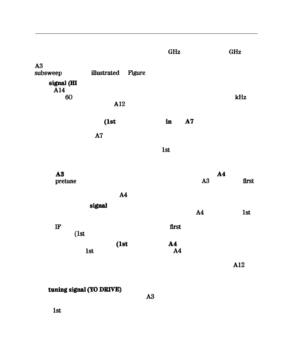
Option 006. These frequencies are generated in subsweeps by phase-locking the
A3
source signal to harmonic multiples of the fractional-N VCO. The high band
subsweep
sequence,
ilhrstrated
in
F’igure
12-5, follows these steps:
1. A signal
(HI
OUT) is generated
by the fractional-N VCQ. The
VCO in
the
Al4
fractional-N assembly generates a CW or swept signal in the range
of 30 to 60 MHz. This signal is synthesized and phase locked to a 100
kHz
reference signal from the
Al2
reference assembly. The signal from the
fractional-N VCO is divided by 1 or 2, and goes to the pulse generator.
2. A comb
of harmonics
(1st
LO) is produced
iu
the A7 pulse generator.
The divided down signal from the fractional-N VCO drives a step recovery
diode (SRD) in the
A7
pulse generator assembly. The SRD multiplies
the fundamental signal from the fractional-N into a comb of harmonic
frequencies The harmonics are used as the
1st
LO (local oscillator) signal to
the samplers One of the harmonic signals is 1 MHz below the start signal set
from the front panel.
3. The
A3
source is pretuued. The source output is fed to the
A4
sampler.
The
pretune
DAC in the All phase lock assembly sets the
A3
source to a
first
approximation frequency (1 to 6 MHz higher than the start frequency). This
signal (RF OUT) goes to the
A4
R input sampler/mixer assembly.
4. The synthesizer sigual and the source signal are combined by the
sampler. A difference frequency
is
generated.
In the A4 sampler, the
1st
LO signal from the pulse generator is combined with the source output signal.
The
IF
(intermediate frequency) produced is a
first
approximation of 1 MHz.
This signal
(1st
IF’) is routed back to the A11 phase lock assembly.
5. The difference frequency (1st IF’) from the
A4
sampler is compared to a
reference.
The
1st
IF feedback signal from the
A4
is filtered and applied to
a phase comparator circuit in the A11 phase lock assembly. The other input
to the phase comparator is a crystal controlled 1 MHz signal from the
Al2
reference assembly. Any frequency difference between these two signals
produces a proportional error voltage.
6. A
tuuiug
signal
(PO
DRIVE) tunes the source and phase lock is achieved.
The error voltage is used to drive the A3 source YIG oscillator, in order to
bring it closer to the required frequency. The loop process continues until
the
1st
IF feedback signal to the phase comparator is equal to the 1 MHz
reference signal, and phase lock is achieved.
Theory of Operation 12-18