‘ICable
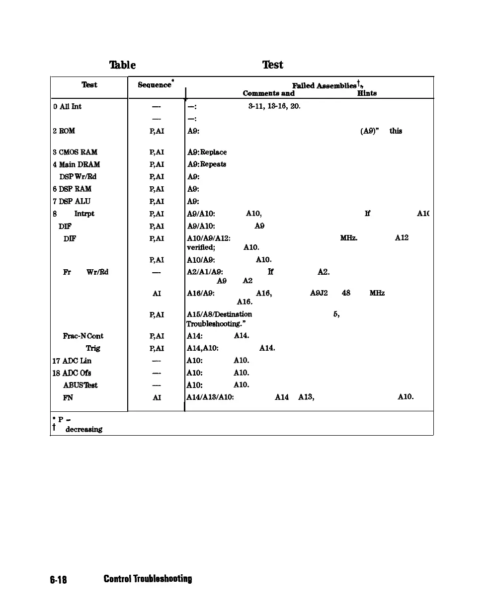
6-2. Internal Diagnostic
‘I&t
with Commentary
lkst
0Allrnt
1 Preset
2IwM
3CMosRAM
QMahlDRAM
5
DSP
WrlRd
6DSPRAM
7DSPALU
8
DSP
Intrpt
9 DIP Control
10 DIP Counter
11 DSP Control
12
Fr
Pan
Wr/Rd
13 Rear Panel
14 Post-reg
15
FYac-N
Cant
16 Sweep
!l’rig
17ADcLin
18ADcofs
19
ABUS
lbst
20 PN count
Seauence’
Probable
Fniled
AwembliPat
I
---
I
Comments
and Troubleshooting
Hints
-:
Executes tests
3-11,13-16,20.
-:
Executes tests 2-11, 14-16. Runs at power-on or preset.
AOz
Repeats on fail; refer to “CPU Troubleshooting
(As)”
in
this
chapter
to replace ROM or A9.
AOt
Beplace
A9.
AOz
Repeats
on fail; replace A9.
AOz
Replace A9.
AOI
Replace A9.
A&
Replace A9.
AO/AlO:
Remove AlO, rerun test. If fail, replace A9.
If
paw, replace AlC
AOiAlO: Most likely A0 assembly.
AlO/AO/AlP:
Check analog bus node 17 for 1
MHz.
If correct,
Al2
is
verified;
suspect
AlO.
AlO/&
Most likely
AlO.
A2iAlIAg:
Run test 23.
lf
fail, replace A2. If pass, problem is on bus
between AS and A2 or on A9 assembly.
AlB/AOz
Disconnect
A16,
and check
A9J2
pin
48
for 4
IdIiz
clock signal.
If OK, replace
A16.
If not, replace A9.
AlS/A8/Destination
assembly: See Chapter
6,
‘Power Supply
Troubleshootiug.”
A14:
Replace
A14.
A14,AlOz
Most likely
A14.
Al&
Replace
AlO.
A10:
Replace
AlO.
AlO: Replace
AlO.
A14lA13/A10:
Most likely
Al4
or
A13,
as previous tests check
AlO.
See
1
Chapter 7, “Source Troubleshooting.”
*P-
part of PRESET sequence; AI -part of ALL INTERNAL sequence.
t
in decreasiug order of probability.
6-16
Digital
ControlTroubleshooting