INS
GUI User’s Manual
Inertial Labs, Inc
TM
Address: 39959 Catoctin Ridge Street, Paeonian Springs, VA 20129 U.S.A.
Tel: +1 (703) 880-4222, Fax: +1 (703) 935-8377 Website: www.inertiallabs.com
113
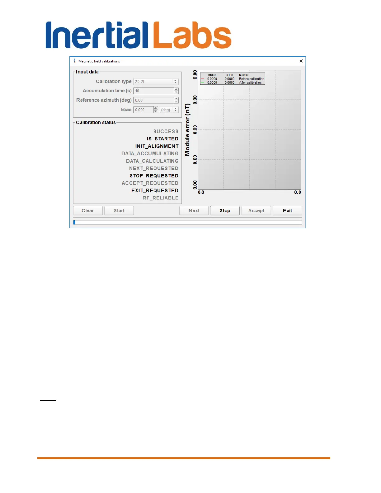
Fig. 10.8
Once the initial alignment is completed, the INS starts accumulating data.
This is signified by the highlighted caption DATA_ACCUMULATING and
the progress bar of data accumulation in the status line (see Fig. 10.9). At
this time, rotation of the carrier object with the INS should be made.
If the 2D calibration is chosen then rotation of the object with the INS in the
horizon plane should be performed (see Fig. 10.4). After time of the data
accumulation expires then result window will appear (see Fig. 10.10)
For 3D calibration the carrier object is rotated in the horizon plane (the Z-
axis is up) with periodical stops about each 90 degrees for tilting in pitch and
roll (see Fig. 10.4 – Fig. 10.6), and then the carrier with the INS is turned
over (the Z-axis is down) and the procedure described above should be
repeated. Tilt angles range depends on the carrier object, but to obtain the
better result increase the angles range as much as possible.
Note: the INS GUI Software provides estimation of 3D calibration quality in terms of
possible INS heading accuracy. To allow this possibility it is necessary to include
additional rotation of the INS with the carrier object in the horizon plane on about 360
degrees or more with pitch and roll near the level. Acceptable pitch and roll change are
set by the “Pitch/Roll threshold” parameter in the “Magnetometers calibration options…”
window Fig. 4.23.

 Loading...