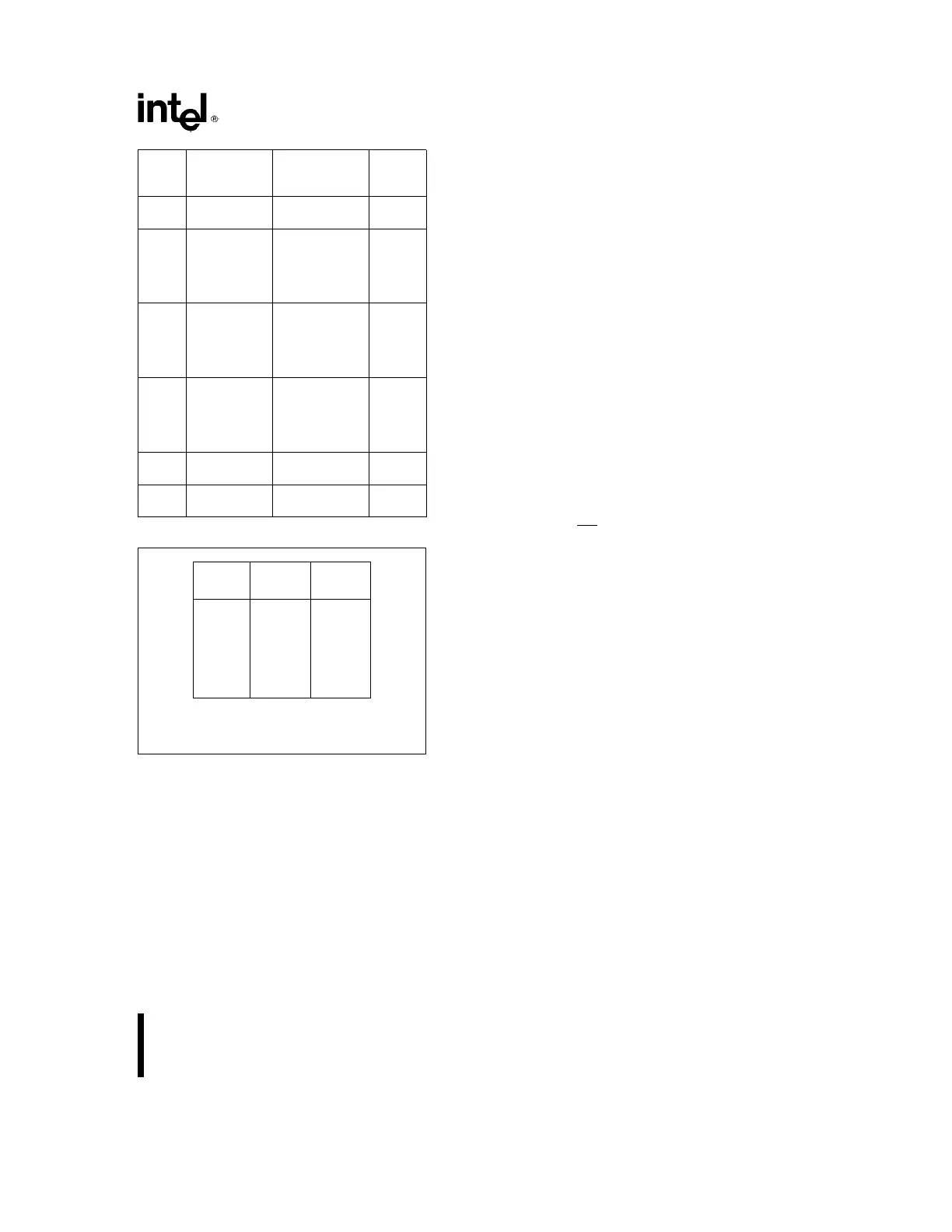
8254
Signal Low
Status Or Going Rising High
Modes Low
0 Disables Ð Ð Enables
Counting Counting
1 Ð Ð 1) Initiates Ð Ð
Counting
2) Resets Output
after Next
Clock
2 1) Disables
Counting Initiates Enables
2) Sets Output Counting Counting
Immediately
High
3 1) Disables
Counting Initiates Enables
2) Sets Output Counting Counting
Immediately
High
4 Disables Ð Ð Enables
Counting Counting
5 Ð Ð Initiates Ð Ð
Counting
Figure 21. Gate Pin Operations Summary
Mode
Min Max
Count Count
010
110
220
320
410
510
NOTE:
0 is equivalent to 2
16
for binary counting and 10
4
for
BCD counting.
Figure 22. Minimum and Maximum Initial Counts
Operation Common to All Modes
PROGRAMMING
When a Control Word is written to a Counter, all
Control Logic is immediately reset and OUT goes to
a known initial state; no CLK pulses are required for
this.
GATE
The GATE input is always sampled on the rising
edge of CLK. In Modes 0, 2, 3, and 4 the GATE input
is level sensitive, and the logic level is sampled on
the rising edge of CLK. In Modes 1, 2, 3, and 5 the
GATE input is rising-edge sensitive. In these Modes,
a rising edge of GATE (trigger) sets an edge-sensi-
tive flip-flop in the Counter. This flip-flop is then sam-
pled on the next rising edge of CLK; the flip-flop is
reset immediately after it is sampled. In this way, a
trigger will be detected no matter when it occursÐa
high logic level does not have to be maintained until
the next rising edge of CLK. Note that in Modes 2
and 3, the GATE input is both edge- and level-sensi-
tive. In Modes 2 and 3, if a CLK source other than
the system clock is used, GATE should be pulsed
immediately following WR
of a new count value.
COUNTER
New counts are loaded and Counters are decre-
mented on the falling edge of CLK.
The largest possible initial count is 0; this is equiva-
lent to 2
16
for binary counting and 10
4
for BCD
counting.
The Counter does not stop when it reaches zero. In
Modes 0, 1, 4, and 5 the Counter ‘‘wraps around’’ to
the highest count, either FFFF hex for binary count-
ing or 9999 for BCD counting, and continues count-
ing. Modes 2 and 3 are periodic; the Counter reloads
itself with the initial count and continues counting
from there.
17