82C54
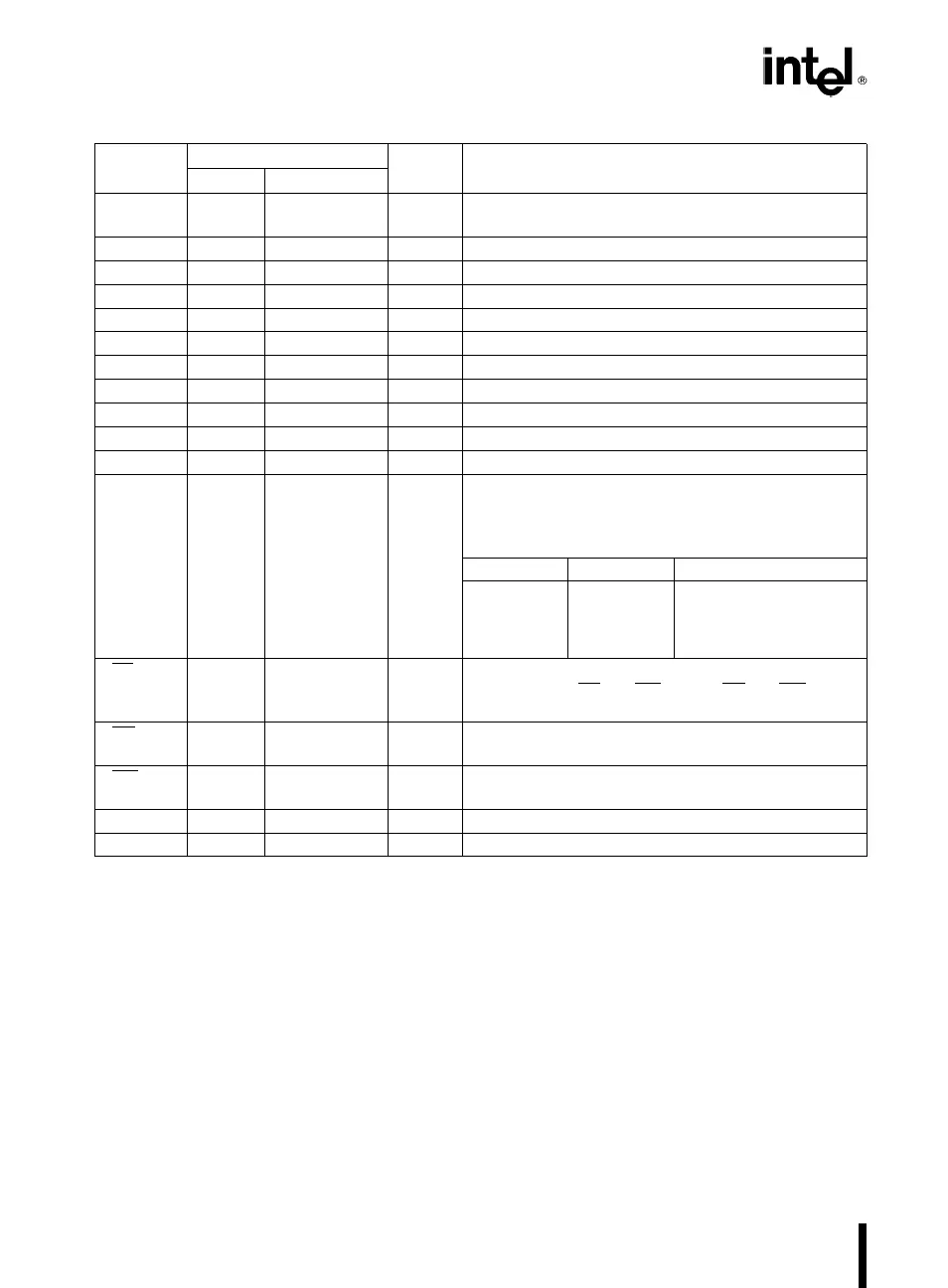
Table 1. Pin Description
Symbol
Pin Number
Type Function
DIP PLCC
D
7
-D
0
1-8 2-9 I/O Data: Bidirectional tri-state data bus lines,
connected to system data bus.
CLK 0 9 10 I Clock 0: Clock input of Counter 0.
OUT 0 10 12 O Output 0: Output of Counter 0.
GATE 0 11 13 I Gate 0: Gate input of Counter 0.
GND 12 14 Ground: Power supply connection.
OUT 1 13 16 O Out 1: Output of Counter 1.
GATE 1 14 17 I Gate 1: Gate input of Counter 1.
CLK 1 15 18 I Clock 1: Clock input of Counter 1.
GATE 2 16 19 I Gate 2: Gate input of Counter 2.
OUT 2 17 20 O Out 2: Output of Counter 2.
CLK 2 18 21 I Clock 2: Clock input of Counter 2.
A
1
,A
0
20-19 23-22 I Address: Used to select one of the three Counters
or the Control Word Register for read or write
operations. Normally connected to the system
address bus.
A
1
A
0
Selects
0 0 Counter 0
0 1 Counter 1
1 0 Counter 2
1 1 Control Word Register
CS 21 24 I Chip Select: A low on this input enables the 82C54
to respond to RD
and WR signals. RD and WR are
ignored otherwise.
RD 22 26 I Read Control: This input is low during CPU read
operations.
WR 23 27 I Write Control: This input is low during CPU write
operations.
V
CC
24 28 Power:
a
5V power supply connection.
NC 1, 11, 15, 25 No Connect
FUNCTIONAL DESCRIPTION
General
The 82C54 is a programmable interval timer/counter
designed for use with Intel microcomputer systems.
It is a general purpose, multi-timing element that can
be treated as an array of I/O ports in the system
software.
The 82C54 solves one of the most common prob-
lems in any microcomputer system, the generation
of accurate time delays under software control. In-
stead of setting up timing loops in software, the pro-
grammer configures the 82C54 to match his require-
ments and programs one of the counters for the de-
sired delay. After the desired delay, the 82C54 will
interrupt the CPU. Software overhead is minimal and
variable length delays can easily be accommodated.
Some of the other counter/timer functions common
to microcomputers which can be implemented with
the 82C54 are:
#
Real time clock
#
Even counter
#
Digital one-shot
#
Programmable rate generator
#
Square wave generator
#
Binary rate multiplier
#
Complex waveform generator
#
Complex motor controller
2