4-10
immediately before returning from the service routine, or if
the AEOI (Automatic End of Interrupt) bit is set, until the trail-
ing edge of the last
INTA. While the IS bit is set, all further
interrupts of the same or lower priority are inhibited, while
higher levels will generate an interrupt (which will be
acknowledged only if the microprocessor internal interrupt
enable flip-flop has been re-enabled through software).
After the initialization sequence, IR0 has the highest priority
and IR7 the lowest. Priorities can be changed, as will be
explained in the rotating priority mode or via the set priority
command.
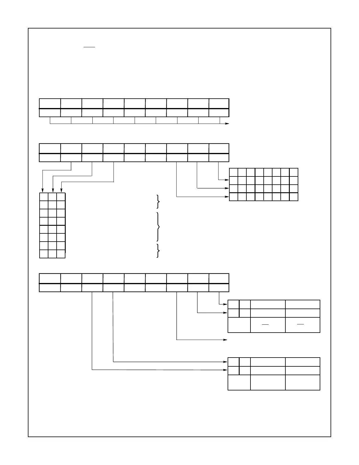
D
7
A
0
D
6
D
5
D
4
D
3
D
2
D
1
D
0
1M
7
M
6
M
5
M
3
M
2
M
1
M
0
M
4
OCW1
Interrupt Mask
1 = Mask set
0 = Mask reset
D
7
A
0
D
6
D
5
D
4
D
3
D
2
D
1
D
0
0 R SL EOI 0 L
2
L
1
L
0
0
OCW2
IR LEVEL TO BE
01 5234 67
01 1010 01
00 0110 11
00 1001 11
001
011
101
100
0
1
1
0
0
1
1
10
0
1
0
Non-specific EOI command
Specific EOI command
Rotate on non-specific EOI command
Rotate in automatic EOI mode (set)
Rotate in automatic EOI mode (clear)
Rotate on specific EOI command
Set priority command
No operation
†
†
†
ACTED UPON
End of interrupt
Automatic rotation
Specific rotation
† L
0
- L
2
are used
D
7
A
0
D
6
D
5
D
4
D
3
D
2
D
1
D
0
0 0 ESMM SMM 1 P RR RIS0
OCW3
0011
1100
No Action
Read IR reg on
next RD pulse
Read IS reg on
next RD pulse
1 = Poll command
0 = No poll command
0011
1100
No Action
Reset special
mask
Set special
mask
READ REGISTER COMMAND
FIGURE 8. 82C59A OPERATION COMMAND WORD FORMAT
SPECIAL MASK MODE
82C59A