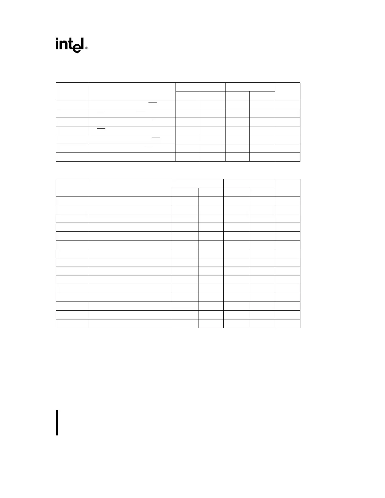
8254
A.C. CHARACTERISTICS T
A
e
0
§
Cto70
§
C, V
CC
e
5V
g
10%, GND
e
0V (Continued)
WRITE CYCLE
Symbol Parameter
8254 8254-2
Unit
Min Max Min Max
t
AW
Address Stable Before WR
v
00ns
t
SW
CS Stable Before WR
v
00ns
t
WA
Address Hold Time After WR
v
00ns
t
WW
WR Pulse Width 150 95 ns
t
DW
Data Setup Time Before WR
u
120 95 ns
t
WD
Data Hold Time After WR
u
00ns
t
RV
Command Recovery Time 200 165 ns
CLOCK AND GATE
Symbol Parameter
8254 8254-2
Unit
Min Max Min Max
t
CLK
Clock Period 125 DC 100 DC ns
t
PWH
High Pulse Width 60
(3)
30
(3)
ns
t
PWL
Low Pulse Width 60
(3)
50
(3)
ns
t
R
Clock Rise Time 25 25 ns
t
F
Clock Fall Time 25 25 ns
t
GW
Gate Width High 50 50 ns
t
GL
Gate Width Low 50 50 ns
t
GS
Gate Setup Time to CLK
u
50 40 ns
t
GH
Gate Setup Time After CLK
u
50
(2)
50
(2)
ns
t
OD
Output Delay from CLK
v
150 100 ns
t
ODG
Output Delay from Gate
v
120 100 ns
t
WC
CLK Delay for Loading
v
055055ns
t
WG
Gate Delay for Sampling
b
550
b
540 ns
t
WO
OUT Delay from Mode Write 260 240 ns
t
CL
CLK Set Up for Count Latch
b
40 45
b
40 40 ns
NOTES:
2. In Modes 1 and 5 triggers are sampled on each rising clock edge. A second trigger within 120 ns (70 ns for the 8254-2) of
the rising clock edge may not be detected.
3. Low-going glitches that violate t
PWH
,t
PWL
may cause errors requiring counter reprogramming.
4. Sampled, not 100% tested. T
A
e
25
§
C.
5. If CLK present at TWC min then Count equals N
a
2 CLK pulses, TWC max equals Count N
a
1 CLK pulse. TWC min to
TWC max, count will be either N
a
1orN
a
2 CLK pulses.
6. In Modes 1 and 5, if GATE is present when writing a new Count value, at TWG min Counter will not be triggered, at TWG
max Counter will be triggered.
7. If CLK present when writing a Counter Latch or ReadBack Command, at TCL min CLK will be reflected in count value
latched, at TCL max CLK will not be reflected in the count value latched.
19