3/24/97 2-12 Architectural Overview
2.5 Instruction Set
The XA instruction set is designed to support common control applications. The instruction
encoding is optimized for the most commonly used instructions: register to register or register
with indirect arithmetic and logic operations; and short conditional and unconditional branches.
These instructions are all encoded as 2 bytes. The bulk of XA instructions are encoded as either 2
or 3 bytes, although there are a few 1 byte instructions as well as 4, 5, and 6 byte instructions.
The execution of instructions normally overlaps instruction fetch, and sometimes write-back
operations, in order to further speed processing.
2.5.1 Instruction Syntax
The instruction syntax chosen for the XA is similar in many ways to that of the 80C51. A typical
XA instruction has a basic mnemonic, such as "ADD", followed by the operands that the
operation is to be performed on. The basic syntax is illustrated in Figure 2.8. The direction of
operation flow is determined by the order in which operands occur in the source line. For
instance, the instruction: "ADD R1, R2" would cause the contents of R1 and R2 to be added
together and the result stored in R1. Since R1 and R2 are word registers in the XA, this is a 16-
bit operation.
An indirect reference (a reference to data memory using the contents of a register as an address)
is specified by enclosing the operand in square brackets, as in: "ADD R1, [R2]". See Figure 2.9.
This instruction causes the contents of R1 and the data memory location pointed to by R2
(appended to its associated segment register) to be added together and the result stored in R1.
Reversing the operand order ("ADD [R2], R1") causes the result to be stored in data memory, as
shown in Figure 2.10.
Most instructions support an additional feature called auto-increment that causes the register
used to supply the indirect memory address to be automatically incremented after the memory
access takes place. The source line for such an operation is written as follows: "ADD R1,
[R2+]". As illustrated in Figure 2.11, the auto-increment amount always matches the data size
used in the instruction. In the previous example, R2 will have 2 added to it because this was a
word operation.
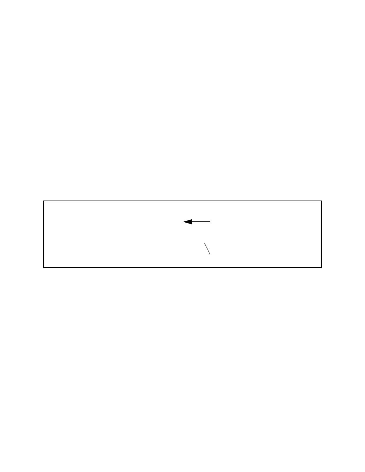
Figure 2.8 Basic Instruction Syntax
op-code
mnemonic
target
operand
source
operand
ADD R1
, R2
operand delimiter (comma)