3/24/97 4-11 CPU Organization
4.4.6 Startup Code
Philips recommends that the first instruction of start-up code set the value of the System
Configuration Register (SCR), described in section 4.3, to reflect the system architecture.
The next recommended step is explicitly initializing the stack pointers. The default values
(section 4.7) are usually insufficient for application needs.
The start-up code sequence may be concluded by a simple branch or jump to application code. A
RETI may not be used at the conclusion of a Reset Exception Interrupt handler (which causes the
start-up code to run) because a reset initializes the SP and does not leave an interrupt stack
frame.
4.4.7 Reset Interactions with XA Subsystems
The following describes how the reset process interacts with some key subsystems:
• Trace Exception. The trace exception is aborted by an external reset; see section 4.9.
• WatchDog. In XA derivatives equipped with a WatchDog timer feature, an internal reset will
be asserted for a derivative-defined number of clocks.
• Resets while in Idle Mode or during normal code execution. Since the XA oscillator is run-
ning in Idle Mode, the
RST input must be kept low for only 10 microseconds (or 10 clocks,
whichever is greater) to achieve a complete reset.
• Resets while in Power-Down Mode. The XA oscillator is stopped in Power-Down mode, so
the
RST input must be low for at least 10 milliseconds. An exception to this is when an exter-
nal oscillator is used and the XA is in Power-Down mode. In this case, if the external oscilla-
tor is running, a reset during Power-Down mode may be the same as a reset in Idle Mode.
4.4.8 An External Reset Circuit
The RST pin is a high-impedance Schmitt trigger input pin. For applications that have no special
start-up requirements, it is practical to generate a reset period known to be much longer than that
required by the power supply rise time and by the XA under all foreseeable conditions. One
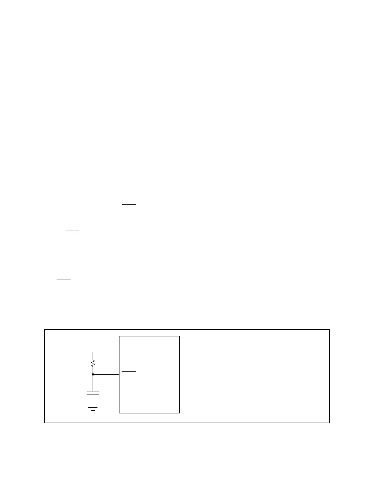
simple way to build a reset circuit is illustrated in Figure 4.7.
Figure 4.7 An external reset circuit
Vdd
C
R
RST
XA
Some typical values for R and C:
R = 100K, C = 1.0µF
R = 1M, C = 0.1µF
(assuming that the Vdd rise time is
1 millisecond or less)