82C54
OPERATIONAL DESCRIPTION
General
After power-up, the state of the 82C54 is undefined.
The Mode, count value, and output of all Counters
are undefined.
How each Counter operates is determined when it is
programmed. Each Counter must be programmed
before it can be used. Unused counters need not be
programmed.
Programming the 82C54
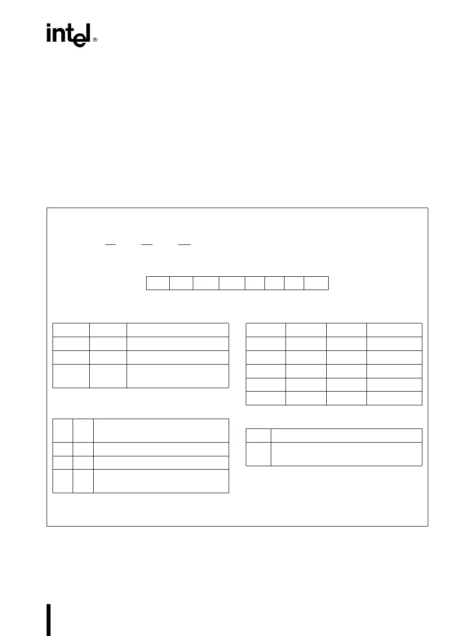
Counters are programmed by writing a Control Word
and then an initial count. The control word format is
shown in Figure 7.
All Control Words are written into the Control Word
Register, which is selected when A
1
,A
0
e
11. The
Control Word itself specifies which Counter is being
programmed.
By contrast, initial counts are written into the Coun-
ters, not the Control Word Register. The A
1
,A
0
in-
puts are used to select the Counter to be written
into. The format of the initial count is determined by
the Control Word used.
Control Word Format
A
1
,A
0
e
11 CS
e
0RD
e
1WR
e
0
D
7
D
6
D
5
D
4
D
3
D
2
D
1
D
0
SC1 SC0 RW1 RW0 M2 M1 M0 BCD
SC Ð Select Counter:
SC1 SC0
0 0 Select Counter 0
0 1 Select Counter 1
1 0 Select Counter 2
11
Read-Back Command
(See Read Operations)
RW Ð Read/Write:
RW1 RW0
0 0 Counter Latch Command (see Read
Operations)
0 1 Read/Write least significant byte only.
1 0 Read/Write most significant byte only.
1 1 Read/Write least significant byte first,
then most significant byte.
NOTE: Don’t care bits (X) should be 0 to insure
compatibility with future Intel products.
M Ð MODE:
M2 M1 M0
0 0 0 Mode 0
0 0 1 Mode 1
X 1 0 Mode 2
X 1 1 Mode 3
1 0 0 Mode 4
1 0 1 Mode 5
BCD:
0 Binary Counter 16-bits
1 Binary Coded Decimal (BCD) Counter
(4 Decades)
Figure 7. Control Word Format
5