82C54
count, all but the first are ignored; i.e., the count
which will be read is the count at the time the first
read-back command was issued.
The read-back command may also be used to latch
status information of selected counter(s) by setting
STATUS
bit D4
e
0. Status must be latched to be
read; status of a counter is accessed by a read from
that counter.
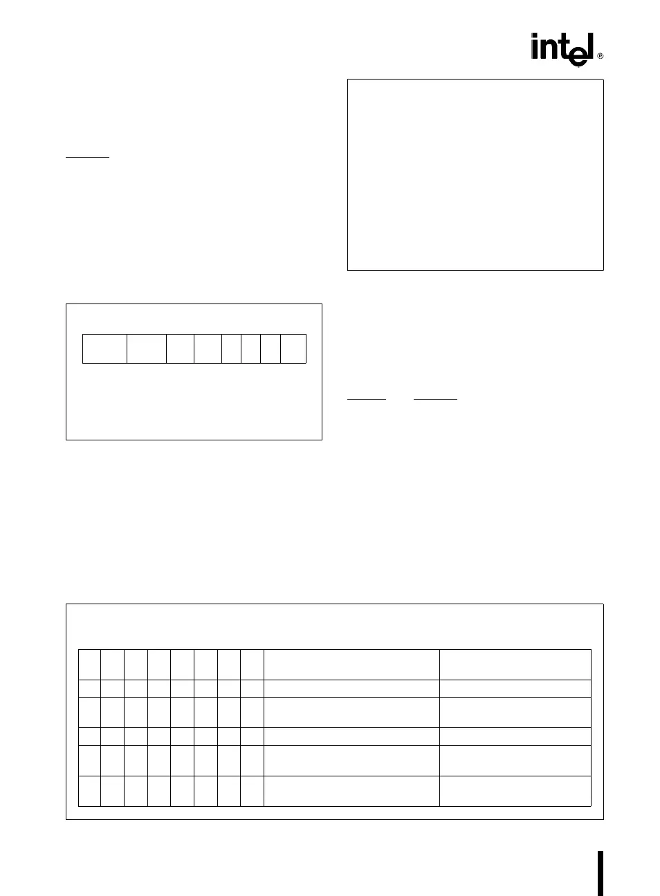
The counter status format is shown in Figure 11. Bits
D5 through D0 contain the counter’s programmed
Mode exactly as written in the last Mode Control
Word. OUTPUT bit D7 contains the current state of
the OUT pin. This allows the user to monitor the
counter’s output via software, possibly eliminating
some hardware from a system.
D
7
D
6
D
5
D
4
D
3
D
2
D
1
D
0
OUTPUT
NULL
RW1 RW0 M2 M1 M0 BCD
COUNT
D
7
1
e
Out Pin is 1
0
e
Out Pin is 0
D
6
1
e
Null count
0
e
Count available for reading
D
5
-D
0
Counter Programmed Mode (See Figure 7)
Figure 11. Status Byte
NULL COUNT bit D6 indicates when the last count
written to the counter register (CR) has been loaded
into the counting element (CE). The exact time this
happens depends on the Mode of the counter and is
described in the Mode Definitions, but until the count
is loaded into the counting element (CE), it can’t be
read from the counter. If the count is latched or read
before this time, the count value will not reflect the
new count just written. The operation of Null Count
is shown in Figure 12.
THIS ACTION: CAUSES:
A. Write to the control
Null count
e
1
word register:
[
1
]
B. Write to the count
Null count
e
1
register (CR);
[
2
]
C. New count is loaded
Null count
e
0
into CE (CR
x
CE);
[
1
]
Only the counter specified by the control word will
have its null count set to 1. Null count bits of other
counters are unaffected.
[
2
]
If the counter is programmed for two-byte counts
(least significant byte then most significant byte) null
count goes to 1 when the second byte is written.
Figure 12. Null Count Operation
If multiple status latch operations of the counter(s)
are performed without reading the status, all but the
first are ignored; i.e., the status that will be read is
the status of the counter at the time the first status
read-back command was issued.
Both count and status of the selected counter(s)
may be latched simultaneously by setting both
COUNT
and STATUS bits D5,D4
e
0. This is func-
tionally the same as issuing two separate read-back
commands at once, and the above discussions ap-
ply here also. Specifically, if multiple count and/or
status read-back commands are issued to the same
counter(s) without any intervening reads, all but the
first are ignored. This is illustrated in Figure 13.
If both count and status of a counter are latched, the
first read operation of that counter will return latched
status, regardless of which was latched first. The
next one or two reads (depending on whether the
counter is programmed for one or two type counts)
return latched count. Subsequent reads return un-
latched count.
Command
Description Results
D
7
D
6
D
5
D
4
D
3
D
2
D
1
D
0
11000010Read back count and status of Count and status latched
Counter 0 for Counter 0
11100100Read back status of Counter 1 Status latched for Counter 1
11101100Read back status of Counters 2, 1 Status latched for Counter
2, but not Counter 1
11011000Read back count of Counter 2 Count latched for Counter 2
11000100Read back count and status of Count latched for Counter 1,
Counter 1 but not status
11100010Read back status of Counter 1 Command ignored, status
already latched for Counter 1
Figure 13. Read-Back Command Example
8